Ford Falcon. Manual - part 203
 

  Index      Ford     Ford Falcon - service repair manual 2002-2005 year


Search            


Content   ..  201  202  203  204   ..


Ford Falcon. Manual - part 203


303-14-26 

Powertrain Control Management 

303-14-26

DESCRIPTION AND OPERATION (Continued)

Testing

EOT Resistance Specification

Temperature

Resistance, k

Ω Voltage Nominal 1.  Connect a WDS tester to the diagnostic

(

±3º C.)

connector.

96

4.5

2.  Check the Parameter Identification (PID) value of

the EOP.

20º

37

3.9

25º

30

3.8

PID Specification

30º

24

3.5

PID

Description

40º

16

3.1

OIL_PRESS

Engine Oil Pressure

60º

7.6

2.2

80º

3.9

1.4

EOP sensor specification

90º

2.8

1.1

Oil Pressure

PID Count

Resistance

100º

2.1

0.9

Normal

Less than 50

Less than 20 

3.  Check the harness for open circuits and short

Low

Greater than

Greater than

circuits.

230

100k

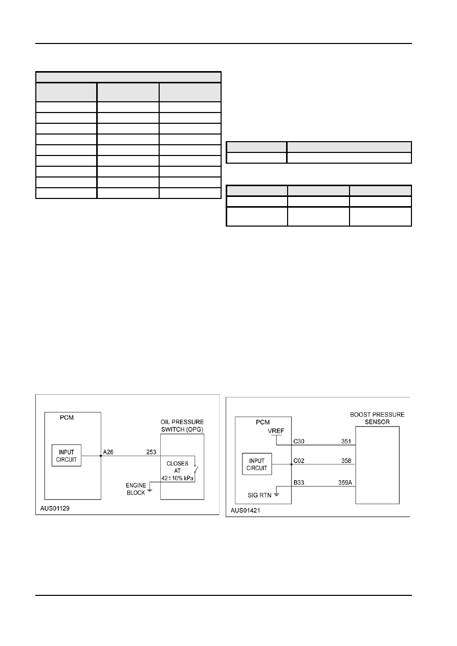
Engine Oil Pressure Sensor

Boost Pressure Sensor, I6 Turbo Engine

The I6 Engine Oil Pressure (EOP) switch is located on

the engine block above and right of the engine oil

The Boost Pressure Sensor (BPS) is located on the

filter. The V8 engine oil pressure switch is located on

aluminium duct between the intercooler and the

the adaptor between the oil filter and the engine

throttle body inlet duct.

block.

The BPS measures the absolute pressure of the

The EOP sensor switches to ground at normal oil

pre-throttle intake system for speed control and

pressures and opens at low engine oil pressure.

wastegate control strategy.

Engine oil pressure is not used for powertrain control

The pressure-sensing element in the BPS employs a

but is transmitted on the CAN for display on the

Piezo resistive sensor that outputs a voltage

instrument cluster to warn the driver the oil pressure is proportional to absolute pressure.

low.

Connections

Connections

PCM Pin C2

…………………..Boost Pressure Signal

PCM Pin A26

…………………… Pressure Signal

PCM Pin C30

… Vehicle Reference Voltage (VREF)

PCM Pin B33..

……………. Signal Return (SIGRTN)

Circuit

Circuit

EOP Sensor Circuit

Failure Mode

Diagnosis

In the event the EOP sensor fail, the instrument

DTCs applicable to this sensor are shown on the

cluster warning lamp will not indicate correctly.

following table.

NOTE: The instrument cluster warning lamp glows

regardless of EOP switch status when the engine is

not running.

G98128 en

303-14-27 

Powertrain Control Management 

303-14-27

DESCRIPTION AND OPERATION (Continued)

the ignition is on, from the Restraint Control Module,

DTC

Test Mode

Condition

RCM. During a non impact phase, the frequency read

P0236

Cont

Boost Pressure

by the PM is 0.8Hz. In the event of an impact that is

Sensor Circuit

registered by the RCM, the RCM changes the

/Range

frequency of the TAS signal to 5Hz for 5 cycles only.

Performance

The PCM detects the change in frequency of the TAS

P0237

KOERKOEO

Boost Pressure

signal and places on the CAN bus in message 427,

Cont

Sensor Circuit

bit 6, where circumstances allow it, a message to the

Low

BEM and the RCM has registered an impact and that

the vehicles doors should be unlocked.

P0238

KOERKOEO

Boost Pressure

Cont

Sensor Circuit

Failure Mode

High

If the TAS signal is not within the normal operating

Failure Mode

frequency range or not present at all, the PCM sets a

DTC in memory for retrieval during self test mode.

The Failure Mode Effects Management (FMEM)

The TAS is tested continuously during vehicle

strategy will, in most cases, ensure reasonable

operation.

operation of the vehicle in the event of a BPS failure.

DTC

Test Mode Condition

If the BPS signal is not within the normal operating

range, or not present at all, the PCM will substitute a

P1534

Cont

TAS signal outside of

default value for pre-throttle absolute pressure and

allowable frequency range or

use MAP for boost control. The appropriate trouble

not present

code will be logged in memory for retrieval during

Self-test mode.

Feedback Inputs

Testing

Heated Exhaust Gas Oxygen Sensor

The BPS is tested continuously during vehicle

On I6 engines, there is one Heated Exhaust Gas

operation (cont.) and whenever Key On Engine Off

Oxygen (HEGO) sensor mounted in the exhaust

(KOEO) or Key On Engine Running (KOER) tests are manifold above the engine pipe connection flange. On

performed.

V8 engines, there are two HEGO sensors, one for

Testing Boost Pressure Sensor

each bank, mounted in the engine pipe just below the

exhaust manifold. The sensor has a built in heating

1.  Connect a WDS tester to the diagnostic

element to bring the sensor to its operating

connector.

temperature quickly and to prevent it from dropping

2.  Check the Parameter Identification (PID) value of

below its operating temperature during periods of

the BPS. If the PID value is within specification,

extended engine idle.

(at key-on engine off it should be at atmospheric

The PCM uses the HEGO sensor signal to adjust the

pressure or 1.8 to 2.2 volts) then check for other

fuel injector pulse width to maintain the air-fuel ratio at

Diagnostic Trouble Code (DTC) or component

stoichiometry. The PCM compares the amount of fuel

faults

that is being used in closed loop operation to the

PID Specification

amount of fuel it predicts would be required if there

was no HEGO signal.

PID

Description

If there is a difference, the PCM adjusts its ‘Open

TURBO

Turbo Boost Pressure

Loop’ (ie. no feedback) predicted values to reflect the

actual requirements of the engine as signaled by the

BPS Specification

HEGO sensor. These corrections are stored in the

Absolute Pressure (kPa)

Signal Voltage (V)

KAM for use when the system next operates in the

open loop mode, ie. in cold drive conditions, or wide

10

0.3

open throttle operation. This adaptive learning

50

1.0

enables the PCM to precisely control the air-fuel ratio

100

1.9

and compensate for component wear and injector

150

2.8

fouling. It does this by having one of its electrodes

exposed to the exhaust gas and the other electrode

200

3.7

exposed to normal air. The difference in the level of

oxygen produces a voltage across the electrodes. The

TAS

platinum electrodes of the Zirconia element typically

operate only above 350ºC so the HEGO sensor has

The TAS signal consists of two distinct frequencies,

heaters permanently switched.

one for normal conditions and a higher frequency for

impact event notification. The PCM recieves a

continuous 12 Volt sqare wave signal on pin B6 while

G98129 en

303-14-28 

Powertrain Control Management 

303-14-28

DESCRIPTION AND OPERATION (Continued)

HEGO Sensor, Typical.

Closed Loop Process

The HEGO detects the amount of unburnt oxygen in

Item

Description

the exhaust gasses as a measure of the air-fuel ratio.

1

Ideal ratio

Since a single sensor is used for a bank of cylinders

2

Oxygen Sensor Signal Lean

the signal represents the average air-fuel ratio. In

Closed Loop Mode the HEGO sensor provides the

3

Increase Pulse Time

PCM with a signal indicating whether the engine is

4

Ideal Ratio

running ‘rich’ or ‘lean’.

5

Oxygen Sensor Signal Rich

HEGO Sensor Operation

6

Reduce Pulse Time

Connections

PCM Pin B8

………..................... HEGO11(I6, V8)

PCM Pin B26

……………............ HEGO11(V8)

PCM Pin B33.................

…..Signal Return (SIGRTN)

Circuit

The PCM uses the HEGO signals to maintain the

correct air-fuel ratio during closed loop mode by

varying the fuel injector pulse width. In open loop

mode the HEGO signal is disregarded by the PCM.

The PCM also stores values from the sensor in a

look-up table as part of its adaptive strategy. See the

‘Operating Modes’ section.

Diagnosis
Diagnostic Trouble Codes (DTC) are retrieved through

the diagnostic connector using the WDS tester.

DTCs applicable to the HEGO sensors are shown in

the following table.

G98129 en

303-14-29 

Powertrain Control Management 

303-14-29

DESCRIPTION AND OPERATION (Continued)

DTC

Test Mode

Condition

HEGO Sensor, I6 Turbo

P0171

KOER

I6, bank

1-V8Fuel

System too lean

P0172

KOER

I6, bank

1-V8Fuel

System too rich

P0174

KOER

V8 bank 2 - Fuel

System too lean

P0175

KOER

V8 bank 2- Fuel

System too rich

P1128

Cont

Connection for

Bank1 and

Bank2 HEGO

sensors

Failure Mode

swapped.

In the event the HEGO fails, the PCM is not able to

HEGO Sensor, I6 Engines

operate in Closed Loop Mode. In Open Loop Mode

the PCM will use values stored in its look-up tables.

These values are stored from the adaptive strategy.
As the strategy constantly updates the table, the PCM

should be able to maintain a suitable air-fuel ratio with

a faulty HEGO.
A trouble code for HEGO failure is only logged when

an Key On Engine Running (KOER) self-test is

performed.

Testing

The HEGO sensors are tested continuously during

vehicle operation (cont.) and whenever Key On

Engine Off (KOEO) or Key On Engine Running

(KOER) tests are performed.

HEGO Sensor, V8 Engines

1.  Connect a WDS tester to the diagnostic

connector.

2.  Check the Parameter Identification (PID) value of

the HEGO sensor. If the PID value is within

specification, then check for other Diagnostic

Trouble Codes (DTC) or component faults.

PID Specification

PID

Description

O2S1

Bank 1 HEGO Voltage

O2S21

Bank 2 HEGO Voltage (V8)

O2S11FM

Bank 1 HEGO Failure

O2S21FM

Bank 2 HEGO Failure

Item

Description

Sensor Test

1

HEGO Sensor (LHS only)

1.  Disconnect the harness from the HEGO sensor

2

HEGO Sensor (LHS & RHS)

connector.

2.  Measure the Heater element resistance across

the heater wire terminals using a suitable

multimeter.

HEGO Sensor Heater Resistance

Specification

G98129 en


Content   ..  201  202  203  204   ..