Ford Falcon. Manual - part 202
 

  Index      Ford     Ford Falcon - service repair manual 2002-2005 year


Search            


Content   ..  200  201  202  203   ..


Ford Falcon. Manual - part 202


303-14-22 

Powertrain Control Management 

303-14-22

DESCRIPTION AND OPERATION (Continued)

the operating range, or not present at all, the PCM will

Circuit

substitute a value proportional to the Throttle Position

Sensor (TP) <TPS> signal and adaptive values stored

within its memory. The appropriate trouble code will

be logged in memory for retrieval during Self-test

mode.

Testing

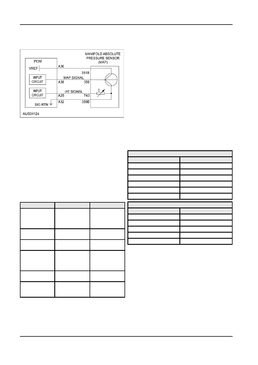
The T-MAP sensor is tested continuously during

vehicle operation (cont.) and whenever Key On

Engine Off (KOEO) or Key On Engine Running

(KOER) tests are performed.

Testing Manifold Absolute Pressure

1.  Connect a WDS tester to the diagnostic

connector.

2.  Check the Manifold Absolute Pressure Sensor

Diagnosis

readout on the screen when the engine is at

If the T-MAP sensor is damaged or faulty, but still

normal operating temperatures. If the value is

operating within the operating range, no fault code will

within specification, then check for other

be logged in memory and value substitution will not

Diagnostic Trouble Codes (DTC) or component

take place. Under these conditions the PCM will

faults.

increase the injector timing in an attempt to

T-MAP Specification (Normally aspirated engines)

compensate; causing difficult starting, rough running

and poor fuel economy.

Manifold Pressure

Signal Voltage

15 kPa

0.3

Incorrect or modified valve timing, worn piston rings or

an alteration in manifold vacuum (particularly at idle)

30 kPa

1.0

can cause a lower than normal vacuum.

50 kPa

2.0

Diagnostic Trouble Codes (DTC) are retrieved through

70 kPa

3.0

the diagnostic connector using the WDS tester.

90 kPa

4.0

DTCs applicable to the T-MAP are shown in the

105 kPa

4.8

following table.

T-MAP Specification (Turbo)

DTC

Test Mode

Condition

Manifold Pressure

Signal Voltage

P0106

KOEO, Throttle

MAP circuit

range /

10 kPa

0.3

performance

50 kPa

1.0

problem

100 kPa

1.9

P0107

KOEO, KOER,

MAP circuit low

150 kPa

2.8

Cont.

input

200 kPa

3.7

P0108

KOEO, KOER,

MAP circuit high

Cont.

input

3.  Check the harness for the conditions described in

P0112

KOEO, KOER

Temperature

‘Fault Finding’ in this section if the displayed

circuit range /

pressure is not within the expected range.

performance

Testing Temperature

problem

P0112

KOEO, KOER,

Temperature

1.  Connect a WDS tester to the diagnostic

Cont.

circuit low input.

connector.

P0113

KOEO, KOER,

Temperature

2.  Check the Intake Air Temperature readout on the

Cont.

circuit high

screen when the engine is at room temperatures

input.

and at normal operating temperatures. If the value

is within specification, then check for other

Failure Mode

Diagnostic Trouble Codes (DTC) or component

faults.

The Failure Mode Effects Management (FMEM)

strategy will, in most cases, ensure almost normal

operation of the vehicle in the event of a T-MAP

sensor fault or failure. If the T-MAP signal is not within

G98127 en

303-14-23 

Powertrain Control Management 

303-14-23

DESCRIPTION AND OPERATION (Continued)

Sensor Test

CMP Sensor Location, V8 Engine

1.  Disconnect the harness from the T-MAP

connector.

2.  Measure the resistance across the connector

terminals using a suitable multimeter. Replace the

sensor if not within specification.

3.  Check the harness for open circuits and short

circuits.

T-MAP Resistance Specification

Temperature

Resistance,

Voltage Nominal

(

±3º C.)

Nominal

5960 

4.3

10º

3820 

4.0

20º

2500 

3.6

Connections

25º

2050 

3.4

PCM Pin 31.......................... CMP1 Sensor Positive

30º

1690 

3.1

PCM Pin 32......... CMP1 Sensor Negative/ SIGRTN

40º

1160 

2.7

PCM Pin 33.......................... CMP2 Sensor Positive

60º

580 

1.8

PCM Pin 32.......... CM2 Sensor Negative/ SIGRTN

Trimming Sensors

Circuit

Camshaft Position Sensor

The 2 engine Camshaft Position Sensor (Cylinder

Identification) (CMP) <CID1,2> are Variable

Reluctance Sensors. On the I6, the 2 sensors are

located on both sides of the cylinder head rear. On

the V8 the sensors are located on the two engine

front covers. The sensors are used in conjunction with

the CKP to synchronize the ignition system and the

fuel injectors to the firing of each cylinder and to

feedback the camshaft position for VCT control.
The I6 engine uses a 3+1 tooth reluctor wheel on the

inlet camshaft and another on the exhaust camshaft.

The V8 engine uses a 4+1 tooth reluctor wheel for the

camshaft on bank 1 and another on the camshaft on

the bank 2.

Diagnosis

CMP Sensor Location, I6 Engine

Diagnostic Trouble Codes (DTC) are retrieved through

the diagnostic connector using the WDS tester.

DTCs applicable to the CMP sensor are shown in the

following table.

DTC

Test Mode

Condition

P0320

Cont.

Ignition engine

speed input

circuit

Malfunction

P0340

Cont.

CID1 Circuit

malfunction

P1340

Cont.

CID2 Circuit

malfunction

G98128 en

303-14-24 

Powertrain Control Management 

303-14-24

DESCRIPTION AND OPERATION (Continued)

Failure Mode

CHT Sensor Location, V8 Engine

Should a CMP signal be missing then the PCM will be

unable to identify the camshaft position and VCT

operation will be disabled. Should both CMP sensors

or signal fail, the PCM will not operate the fuel

injectors sequentially, and the engine may run rough.

Testing

The CMP sensor is tested continuously during vehicle

operation (cont.).
1.  Connect a WDS tester to the diagnostic

connector.

2.  Check the Parameter Identification (PID) value of

the CMP. If the PID value is within specification,

then check for other Diagnostic Trouble Codes

The CHT sensor measures the cylinder head

(DTC) or component faults.

temperature for the fail-safe cooling strategy. The

PID Specification

PCM also uses this sensor signal in conjunction with

the Intake Air Temperature signal to determine fuel

PID

Description

requirements and to inhibit activation of some features

that only work properly when the engine is at normal

CMPFM

CMP Failure mode flag

operating temperature. These feature include closed

SYNC

CMP and CKP signals are

loop fuel control and canister purge control.

synchronised

The sensor employs a thermistor that is sensitive to

temperature variations. The resistance of the

Sensor Test

thermistor decreases as the temperature rises.

1.  Disconnect the harness from the CMP Sensor

Connections

connector.

2.  Measure the resistance across the connector

PCM Pin A45.................... CHT Temperature Signal

terminals using a suitable multimeter. Replace the PCM Pin A32.....................Signal Return (SIGRTN)

sesnor if not within specification.

Circuit

CMP Resistance Specification

280 - 380 

3.  Check the harness for open circuits and short

circuits.

Cylinder Head Temperature Sensor

The Cylinder Head Temperature (CHT) sensor is

mounted at the rear of the cylinder head on the I6 and

between cylinder 3 & 4 on the cylinder head of the V8

engines.

CHT Sensor Location, I6 Engine

Diagnosis
The CHT sensor element is encased is brass for

protection against corrosion. Diagnostic Trouble

Codes (DTC) are retrieved through the diagnostic

connector using the WDS tester.

DTCs applicable to the CHT sensor are shown in the

following table.

G98128 en

303-14-25 

Powertrain Control Management 

303-14-25

DESCRIPTION AND OPERATION (Continued)

Connections

DTC

Test Mode

Condition

P0116

KOEO, KOER

circuit range /

PCM Pin A13

……..……………… …… EOT Signal

performance

PCM Pin A32

…..…………. Signal Return (SIGRTN)

problem

Circuit

P0117

KOEO, KOER,

circuit low input

Cont.

P0118

KOEO, KOER,

circuit high input

Cont.

Failure Mode (Petrol Engines only)

The PCM has a Failure Mode Effects Management

(FMEM) strategy mode that, in most cases, will

ensure almost normal operation of the vehicle in the

event of a CHT sensor fault or failure. If the CH

sensor fails or produces an invalid signal, the PCM

will not be able to sense the engine temperature.

Under these conditions, the PCM will substitute the

value from the Intake Air Temperature Sensor (IAT).

During crank mode, the PCM will substitute the IAT

signal for the missing CHT, since both sensors will

have “soaked” to approximately the same

Diagnosis

temperature. When the engine is switched OFF, the

If the sensor is damaged or faulty, but still operating

whole engine will soak up heat from the cooling

within the operating range, no fault code will be

system and reach a similar temperature. When the

logged DTCs applicable to this sensor are shown on

engine starts, the PCM will infer a value for the CHT

the following table.

of approximately 80º C.

DTC

Test Mode

Condition

Testing

0196

KOEO

Engine Oil

The CHT sensor is tested continuously during vehicle

Temperature

operation (cont.) and whenever Key On Engine Off

Sensor

(KOEO) or Key On Engine Running (KOER) tests are

temperature is

performed.

inconsistent with

1.  Connect a WDS tester to the diagnostic

engine

connector.

temperature

2.  Check the Cylinder Head Temperature readout on

Failure Mode

the screen when the engine is at normal operating

temperatures.

The Failure Mode Effects Management (FMEM)

strategy will, in most cases, ensure normal operation

PID

Description

of the vehicle in the event of an EOT sensor failure. If

Cylinder Head

85

° to 100°

the EOT signal is not within the normal operating

Temperature

range, or not present at all, the PCM will substitute a

temperature value calculated from CHT. The

Engine Oil Temperature Sensor

appropriate trouble code will be logged in memory for

retrieval during Self-test mode.

The Engine Oil Temperature (EOT) sensor is located

on the engine block directly above the engine oil filter

Testing

(I6) and on the engine sump on the V8 engine.

The EOT sensor is tested continuously during vehicle

The EOT sensor measures the temperature of the

operation (cont.) and whenever Key On Engine Off

engine oil for the variable cam timing strategy.

(KOEO) or Key On Engine Running (KOER) test are

A temperature-sensing element is incorporated into

performed.

the EOT sensor to measure the temperature of the

Testing Engine Oil Temperature Sensor

engine oil within the engine. The temperature element

employs a thermistor that is sensitive to temperature

1.  Disconnect the EOT sensor wire connector.

variations. The resistance of the thermistor decreases 2.  Measure the resistance across the connector

as the temperature rises.

terminals using a suitable multimeter. Replace the

sensor if not within specification.

G98128 en


Content   ..  200  201  202  203   ..