Ford Falcon. Manual - part 26
 

  Index      Ford     Ford Falcon - service repair manual 2002-2005 year


Search            


Content   ..  24  25  26  27   ..


Ford Falcon. Manual - part 26


204-01-11 Front 

Suspension 204-01-11

REMOVAL AND INSTALLATION (Continued)

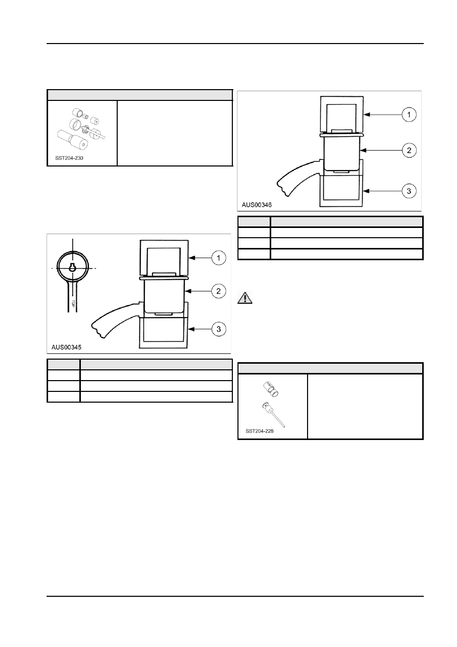
3.  Place the shaft of the installer 204-230-Item 8 into

Lower Arm - Large Bushing

the bush.

Special Tools

204-230

Installation
Large bush

1.  Position large bush in arm orientating keyway

along central access of arm.
NOTE: Large bush keyway must be positioned 

±

Item

Description

5

° from centreline of control arm.

1

Installer 202-230-Item 8

2

Small Bush

3

Receiver 204-230-Item 3

4.  Using a hydraulic press and suitable “V” blocks

place a steel plate over the installer and press the

bush home (2.5-3 tonne req’d).

 CAUTION: Always wear safety glasses and

try to protect your body by placing yourself at the

side of the press frame during operation or use a

transparent ballistic nylon protective blanket

1230PB.

Upper Arm Bushing

Item

Description

Special Tools

1

Installer 204-230-Item 1

204-228

2

Large Bush

3

Receiver 204-230-Item 10

2.  Place the open side of the installer 204-230-Item

2 onto the bush.

3.  Place receiver 204-230-Item 10 under the arm,

cup upwards.

Removal

4.  Using a hydraulic press on the installer press the

bush home (2.5-3 tonne req’d).

NOTE: For introduced at AV Falcon are different

bushes in front of arm to rear of arm. Front bushes

Installation

are visually different & are voided around the

Small bush

circumference.

1.  Position small bush in arm.

NOTE: Eye protection must be worn during the

2.  Place the receiver 204-230-Item 3 cup upward

following procedures.

onto the shaft of the installer 204-230-Item 8.

G48701 en

204-01-12 Front 

Suspension 204-01-12

REMOVAL AND INSTALLATION (Continued)

1.  Support receiver tool 204-228-Item 1 under bush. 3.  Insert mandrel 204-228-Item 2 into bush sleeve.

Insert aligning bush 204-228-Item 3 into bottom of

receiver. Proceed to push bush out until it

releases itself from the upper arm casting.

Item

Description

1

Upper control arm

2

Receiver 204-228-Item 1

Item

Description

2.  Press receiver tool 204-228-Item 1 onto bush until 1

Mandrel 204-228-Item 2

it supports on casting.

2

Aligning bush 204-228-Item 3

Installation
NOTE: 
Insert voided bush into forward housing in

arm. Insert non-voided bush into rear housing in arm.

1.  Place receiver tool 204-228-Item 1 under upper

control arm.

2.  Insert aligning bush 204-228-Item 3 into receiver.
3.  Insert reducing bush tool 204-228-Item 4 on top of

upper control arm.

4.  Insert suspension bush onto mandrel

204-228-Item 2 and insert into reducing bush.

5.  Lubricate bush in soapy water.

Item

Description

1

Upper control arm

2

Receiver 204-228-Item 1

G48701 en

204-01-13 Front 

Suspension 204-01-13

REMOVAL AND INSTALLATION (Continued)

6.  Insert bush until bush is correctly inserted into

Item

Description

upper control arm.

4

Aligning bush 204-228-Item 3

NOTE: Correct insertion can be viewed by cutouts 5

Reducing bush 204-228-Item 4

in receiver. Bush should be central to the control

arm.

Front Wheel Spindle and Hub

Removal
1.  Raise the vehicle and support it under the body

rails.

2. Remove 

the 

wheel.

3.  Remove the brake caliper from the spindle and

suspend it so that there is no strain on the brake

hose.

4.  Remove the hub and disc from the spindle.
5.  Loosen the tie rod end nut and using a taper

breaker free the stud taper. Remove the nut and

detach the tie rod end from the spindle.

6.  Loosen the nuts on the spindle ball joint studs and

free the tapers using a taper breaker.

7.  Remove the bolt and nut securing the upper ball

joint stud and move the stud out of the spindle.

8.  Remove the nut from the lower ball joint stud and

remove the spindle from the vehicle.

Installation
1.  Locate the lower ball joint stud into the spindle

and attach the nut.

2.  Locate the upper ball joint stud into the spindle

and fit the clamp bolt and nut.

3.  Torque the nuts to specification.
4.  Install the tie rod end in the spindle. Torque the

nut.

5.  Install the hub and disc on the spindle. Torque nut

to specification.

Item

Description

6.  Install the brake caliper.

1

Mandrel 204-228-Item 2

7.  Install the wheel and lower the vehicle.

2

Upper control arm

3

Receiver 204-228-Item 1

G48702 en

204-01-14 Front 

Suspension 204-01-14

REMOVAL AND INSTALLATION (Continued)

Item

Description

1

Nut M14x2

2

Bolt and Retainer

3

Arm Assembly Front Susp. Lower

4

Nut Lock

5

Spindle Assembly

6

Nut 3/8-24 UNF

7

Stabilizer Bar Link

8

Nut

9

Front Stabilizer Bar

10

Bolt M8x26

11

Stab. Bar Mounting Bracket

Item

Description

1

Hub & Bearing Assy Frt Brake

2

Nut & Washer Assy

3

Seal Frt Wheel Hub

4

Spindle Assy Frt Wheel

G48702 en


Content   ..  24  25  26  27   ..