Ford Falcon. Manual - part 24
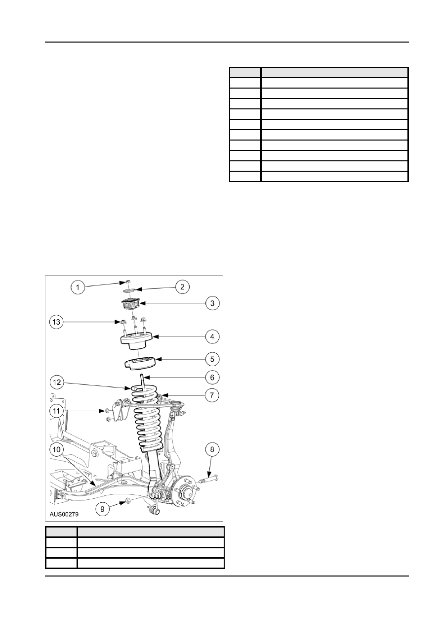
204-01-3 Front
Suspension 204-01-3
DESCRIPTION AND OPERATION
Item
Description
Front Suspension
4
Bracket Assy
Suspension
5
Insulator
The suspension is so designed that it allows an
6
Shock Absorber Frt
individual wheel to compensate for changes in the
7
Arm & Shaft Assy Frt Susp Upr
road’s surface level without considerably affecting the
8
Bolt Hex M14
opposite wheel. Each wheel is independently
9
Nut M14
connected to the frame and body by a spindle, ball
joint assemblies, and upper and lower control arms.
10
Arm Assy Frt Susp Lwr
The control arms are specifically designed and
11
Nut M10 Flange
positioned to allow the steering spindle to move in a
12
Spring Frt Susp Coil
prescribed three dimensional arc. The front wheels
13
Nut
are held in proper relationship to each other by two tie
rods that are connected to the steering rack and to
Side roll of the suspension is controlled by a spring
the spindles.
steel stabilizer bar. It is mounted in rubber bushings
held to the frame side rails by brackets.
Coil chassis springs are mounted between the spring
housings on the front end sheet metal and the spring
The ends of the stabilizer are connected to the lower
seats that are integral with the shock absorber body.
control arms. Rubber grommets at these connections
Ride control is provided by double, direct acting shock provide flexibility and ride features.
absorbers mounted inside the coil springs and
The upper control arm is attached to the body through
attached to the lower control arms by bolts. The upper isolating rubber bushings connected to brackets that
portion of each shock absorber extends through the
are bolted to the body.
dual path shear mount and is secured with two
The upper ball joint is a press fit into the upper control
grommets, two grommet retainers, and a nut.
arm, and the stud is fitted into the upper control end of
the spindle forging. A nylok nut and bolt clamps the
spindle to the ball joint.
The lower ball joint is a press fit into the lower arm,
and secures to the lower end of the spindle forging by
a tapered stud and nylok nut.
The inner ends of the lower control arms have
pressed in bushings and are attached to the cross
members by a single bolt through each bushing.
The suspension mounting points are all rubber
insulated to minimise the transmission of road noise
and vibration to the vehicle body.
Compliance in the lower arm bushes permits the
wheel a small amount of fore and aft movement and
so reduce the shock loading on the steering linkage
when the wheel hits a sudden irregularity in the road
surface.
Item
Description
1
Nut
2
Washer
3
Insulator
G48691 en