Ford Falcon. Manual - part 25
204-01-7 Front
Suspension 204-01-7
REMOVAL AND INSTALLATION (Continued)
3. Attach the ball joint to the spindle, tighten the
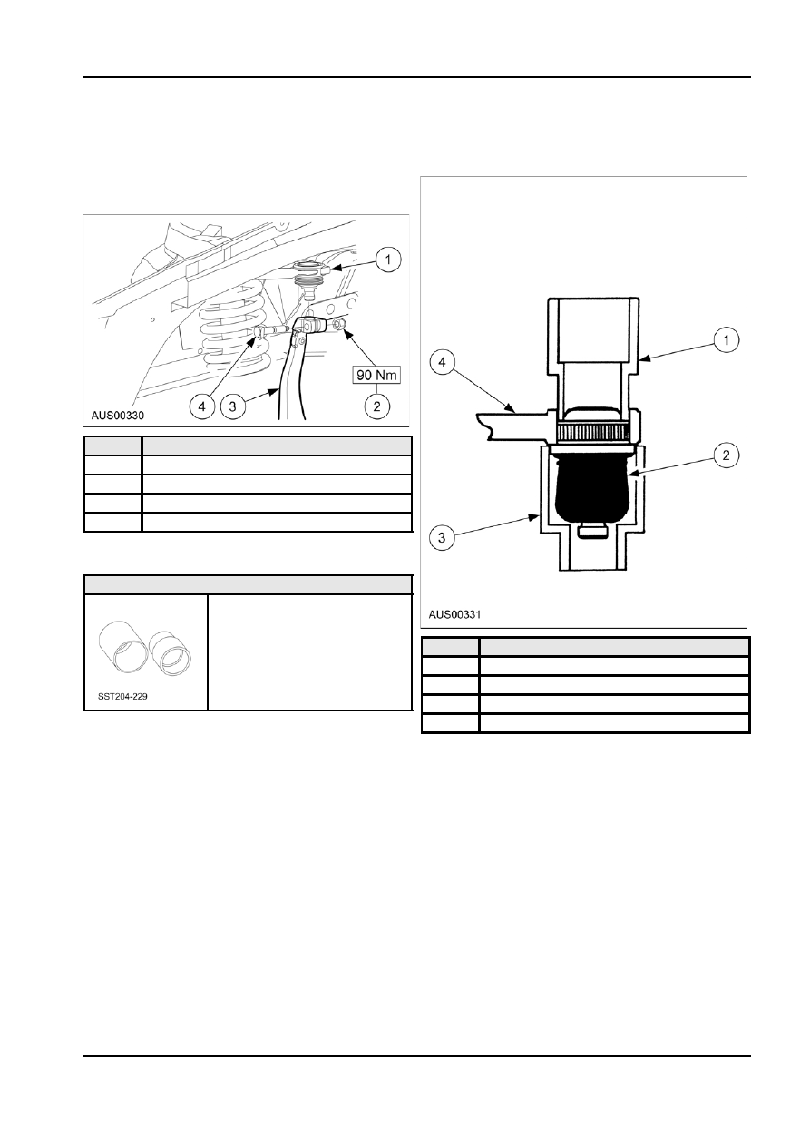
2. Using a hydraulic press with two tonne approx.
clamp joint. Remove the spindle tie.
force push out ball joint using tool 204-229-2,
small diameter down.
4. Install the wheel and lower the vehicle.
5. With the vehicle at curb attitude tighten the
spindle pivot bolts to specification.
Item
Description
1
Arm Assy Frt Susp Upper
2
Receiver Bolt
3
Spindle Assy
4
Nut
Upper Control Arm Ball Joint
Special Tools
204-229
Item
Description
1
204-229-Item 2
2
Ball Joint
3
204-229-Item 1 Receiver
4
Upper Control Arm
Removal
NOTE: Eye protection must be worn during the
Installation
following procedures.
1. Remove rubber boot from the new ball joint,
ensuring not to damage the boot or retainer ring
1. Place receiver 204-229-Item 1 large diameter
clip.
facing up, under upper arm casting.
2. Position ball joint over control arm.
3. Place receiver 204-229-Item 1, small end up,
under upper arm casting.
4. Using a hydraulic press push ball joint home with
tool 204-229-Item 2 large end facing down.
G48695 en