Fiat 500X (2022 year). Manual in english - page 4
 

  Index      Manuals     Fiat 500X (2022 year). Manual in english


Search            copyright infringement  


Content      ..     2      3      4      5     ..


Fiat 500X (2022 year). Manual in english - page 4


GETTING TO KNOW YOUR VEHICLE

55

SUNROOF — IF EQUIPPED  

The sunroof has two glass panels (the front one is 

operational and the rear one fixed) and is 

equipped with two manual operated sunshades, 

front and rear.
The power sunroof can be operated only when the 

ignition is placed in ON/RUN.
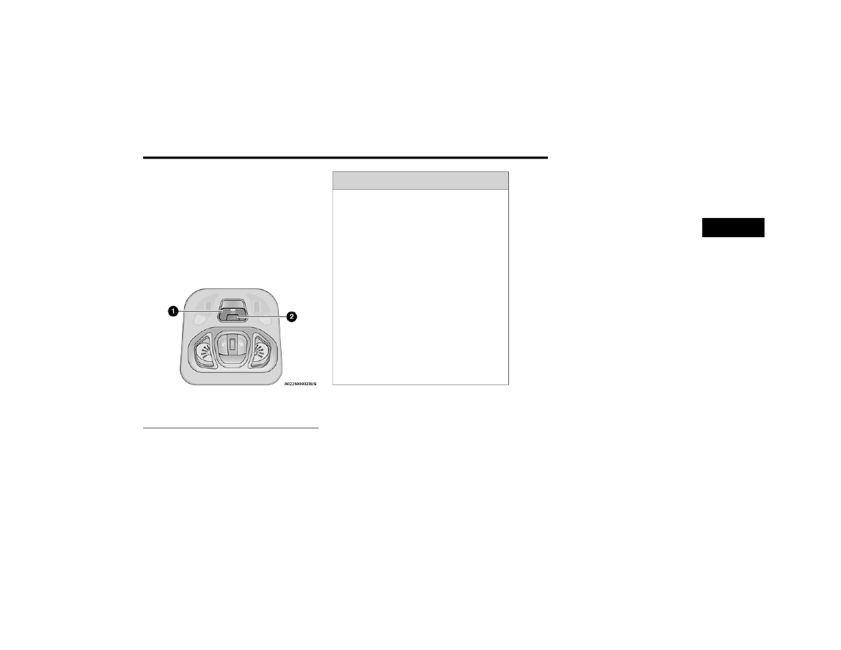
The power sunroof switches are located in the 

overhead console.

Operation Switch

O

PENING

 A

ND

 C

LOSING

 T

HE

 S

UNROOF

To retract the front panel to the open position, 

push the open/close switch and the sunroof will 

fully open. The sunroof can be stopped in any 

position by pushing the switch a second time while 

is opening.
To close the front panel completely, pull the open/

close switch from the open position. The sunroof 

can be stopped in any position by pulling the 

sunroof switch a second time while it is closing.

P

INCH

 P

ROTECT

 F

EATURE

This feature will detect an obstruction in the 

opening of the sunroof during Express Close 

operation. If an obstruction in the path of the 

sunroof is detected, the sunroof will automatically 

retract. Remove the obstruction if this occurs.

V

ENTING

 S

UNROOF

To vent the sunroof, push the vent switch.
NOTE:

The vent switch has the automatic function only at 

the opening of the sunroof. During the closing of 

the sunroof, the switch must be held until closed.

1 — Front Panel Open/Close Switch
2 — Front Panel Vent Switch

WARNING!

Never leave children alone in a vehicle, or with 

access to an unlocked vehicle. Never leave 

the key fob in or near the vehicle or in a loca

-

tion accessible to children. Occupants, partic

-

ularly unattended children, can become 

entrapped by the power sunroof while oper

-

ating the power sunroof switch. Such entrap

-

ment may result in serious injury or death.

In a collision, there is greater risk of being 

thrown from a vehicle with an open sunroof. 

You could also be seriously injured or killed. 

Always fasten your seat belt properly and 

make sure all passengers are properly 

secured too.

Do not allow small children to operate the 

sunroof. Never allow your fingers, other body 

parts, or any object to project through the 

sunroof opening. Injury may result.

2

-------------------------------------------------------------------------------------------------------------------------------------------------------------

56

GETTING TO KNOW YOUR VEHICLE


S

UN

 S

HADE

The two sun shades are manually operated and 

can be adjusted in any position.

S

UNROOF

 M

AINTENANCE

Use only a non-abrasive cleaner and a soft cloth to 

clean the glass panel. Periodically check for and 

clear out any debris that may have collected in the 

tracks.

E

MERGENCY

 O

PERATION

If the power sunroof switch fails, the sunroof can 

be operated manually as follows:
1. Remove the protective cap located on the 

inner lining.

2. Remove the Allen Key that is supplied in the 

tool bag in the cargo area.

3. Insert the Allen Key into the key hole and turn 

it clockwise to open the roof or 

counter-clockwise to close.

Allen Key And Key Hole

P

OWER

 S

UNROOF

 R

ELEARN


P

ROCEDURE

As a result of any abnormal behavior of the roof or 

as a result of an emergency operation, and you 

must relearn the automatic operation of the 

sunroof.
Proceed as follows:
1. Push the open/close button to move the roof 

in the fully closed position.

2. Place the ignition in the OFF position and wait 

for at least 10 seconds.

3. Place the ignition in the ON/RUN position.
4. Pull the open/close button and hold it for at 

least 10 seconds, after which you should feel 

the mechanical stop of the electric motor of 

the roof.

5. Within five seconds, pull to close and hold the 

open/close button. The roof makes a complete 

cycle of opening and closing automatically (to 

indicate that the relearn procedure has been 

successful). If this does not happen, you need 

to repeat the procedure from the beginning.

1 — Allen Key
2 — Key Hole

CAUTION!

When refitting sunroof, be careful to avoid 

fingers, scarves, ties and items of clothing 

from getting caught under the panel.

Do not open the roof in the presence of snow 

or ice. There is risk of damage.

-------------------------------------------------------------------------------------------------------------------------------------------------------------

GETTING TO KNOW YOUR VEHICLE

57

POWER FOLDING ROOF — IF EQUIPPED

If your vehicle is equipped with a Power Folding 

Roof, the control switch can be found on the 

overhead console.

Power Folding Roof Open/Close Switch

NOTE:

The Power Folding Roof is non-removable.

The Power Folding Roof will not open in 

temperatures below -2°F (-18°C) or above 

176°F (80°C).

The Power Folding Roof will not operate at 

vehicle speeds above 62 mph (100 km/h).

NOTE:

A slight pause in audio may be heard when 

opening and closing the Power Folding Roof as a 

result of the Uconnect system switching between 

Power Roof Closed and Power Roof Open audio 

modes.

O

PENING

 T

HE

 P

OWER

 F

OLDING

 R

OOF

Express Mode
Push the open/close switch and release it within 

one-half second and the power roof will open 

automatically from any position. The power roof 

will open fully and stop automatically. Push the 

open/close switch and release it within one-half 

second and the sunroof will close automatically 

from any position and it stops 7.9 inches (20 cm) 

before full closure. For full closure, push and hold 

the open/close switch.
During Express Open or Express Close operation, 

any other movement of the power roof switch will 

stop the sunroof.
Manual Mode
To open the power roof manually, push and hold 

the open/close switch to the full open position, 

then release. To close the power roof manually, 

push and hold the open/close switch to the fully 

closed position, then release.
Any release of the switch during open or close 

operation will stop the power roof movement. The 

power roof will remain in a partially opened 

position until the switch is operated and held 

again.

WARNING!

Never leave children unattended in a vehicle, 

or with access to an unlocked vehicle. Never 

leave the key fob in or near the vehicle, or in a 

location accessible to children. Do not leave 

the Keyless Enter ‘n Go™ Ignition in the ACC or 

ON/RUN position. Occupants, particularly 

unattended children, can become entrapped 

by the power roof while operating the power 

roof switch. Such entrapment may result in 

serious injury or death.

In a collision, there is a greater risk of being 

thrown from a vehicle with an open power 

roof. You could also be seriously injured or 

killed. Always fasten your seat belt properly 

and make sure all passengers are also prop

-

erly secured.

Do not allow small children to operate the 

power top. Never allow your fingers, other 

body parts, or any object, to project through 

the power roof opening. Injury may result.

2

-------------------------------------------------------------------------------------------------------------------------------------------------------------

58

GETTING TO KNOW YOUR VEHICLE


C

LOSING

 T

HE

 P

OWER

 R

OOF

Express Mode
Push the close switch and release it within one-half 

second. The power roof will close fully and stop 

automatically. This is called “Express Close”. 

During Express Close operation, any movement of 

the switch will stop the power roof.
Manual Mode
To close the power roof manually, push and hold 

the close switch. The power roof will move forward 

and automatically stop at the fully closed position. 

Any release of the switch will stop the movement. 

The power roof will remain in a partially closed 

position until the switch is pushed and held again.
If the power roof switch fails, the sunroof can be 

operated manually. See,  

Ú

page 56 for further 

information.

P

OWER

 R

OOF

 M

AINTENANCE

Use only a non-abrasive cleaner and a soft cloth to 

clean the window glass. For important information 

on cleaning and caring for your vehicle  

Ú

page 286.

I

GNITION

 O

FF

 O

PERATION

The power sliding roof switch can remain active in 

Accessory Delay for up to approximately 

10 minutes after the vehicle’s ignition is placed to 

the OFF position. Opening either front door will 

cancel this feature.
NOTE:

Ignition Off timing is programmable through the 

Uconnect system  

Ú

page 123.

R

ELEARN

 P

ROCEDURE

For vehicles equipped with a power sliding roof, 

there is a relearn procedure that allows you to 

calibrate the power roof when the “Express Mode” 

stops working. To reset the power sliding roof, 

follow these steps:
1. Place the ignition in the RUN position, and 

start the vehicle.

NOTE:

The engine must be running to perform the relearn 

procedure.
2. Ensure the power sliding roof is in the fully 

closed position.

3. Push and hold the open/close switch for 

10 seconds. This will put the power sliding roof 

into calibration mode.

4. Continue holding down the close button while 

the top goes fully open and then back to fully 

close.

5. Once the power sliding roof has stopped in the 

fully closed position, release the open/close 

switch. The power sliding roof is now reset and 

ready to use.

NOTE:

If the open/close switch is released anytime during 

the relearning process, the relearn may not be 

complete, and the procedure must be repeated.

HOOD    

T

O

 O

PEN

 T

HE

 H

OOD

To open the hood, two latches must be released.
1. Pull the release lever located underneath the 

driver’s side of the instrument panel.

Hood Release Lever

-------------------------------------------------------------------------------------------------------------------------------------------------------------

GETTING TO KNOW YOUR VEHICLE

59

2. Move to the outside of the vehicle and push 

the safety latch release lever toward the 

passenger side of the vehicle. The hood 

release lever is located behind the center front 

edge of the hood.

Safety Latch Release Lever Location

3. Remove the support rod from the locking tab 

and insert it into the seat located on the 

underside of the hood. Be sure the rod is 

locked into position.

Hood Prop System

T

O

 C

LOSE

 T

HE

 H

OOD

1. Hold up the hood with one hand and with the 

other hand remove the support rod from its 

seat and reinsert it into the locking tab.

2. Lower the hood to approximately 12 inches 

(30 cm) from the engine compartment and 

drop it. Make sure that the hood is completely 

closed.

1 — Locking Tab
2 — Support Rod
3 — Support Rod Seat

WARNING!

Be sure the hood is fully latched before driving 

your vehicle. If the hood is not fully latched, it 

could open when the vehicle is in motion and 

block your vision. Failure to follow this warning 

could result in serious injury or death.

CAUTION!

To prevent possible damage, do not slam the 

hood to close it. Lower hood to approximately 

12 inches (30 cm) and drop the hood to close. 

Make sure hood is fully closed for both latches. 

Never drive vehicle unless hood is fully closed, 

with both latches engaged.

2

-------------------------------------------------------------------------------------------------------------------------------------------------------------

60

GETTING TO KNOW YOUR VEHICLE


LIFTGATE

T

O

 U

NLOCK

/O

PEN

 T

HE

 L

IFTGATE

To unlock the liftgate from the outside, push the 

electronic liftgate release and pull the liftgate open 

with one fluid motion.

Electronic Liftgate Release

When opening the door, the interior dome light will 

illuminate. The interior dome light will turn off 

automatically by closing the liftgate  

Ú

page 38.

If the liftgate is left open, the interior dome light will 

shut off after a few minutes to conserve battery 

life.
Emergency Opening
Proceed as follows:
1. Lower the headrests and fold the seatbacks.

1 — Yellow Tab

2. Using the supplied screwdriver (located under 

cargo floor in tool kit), remove the yellow tab 

from the liftgate latching mechanism.

3. With the yellow tab removed, insert the 

screwdriver into the now open release tab slot 

to trigger the release of the liftgate.

2 — Release Tab Slot

L

OCK

/C

LOSE

 T

HE

 L

IFTGATE

Grab the liftgate closing handle and lower the 

liftgate.

Liftgate Closing Handle

NOTE:

Before closing the liftgate, make sure to be in 

possession of the key fob because the liftgate will 

be locked automatically.

-------------------------------------------------------------------------------------------------------------------------------------------------------------

GETTING TO KNOW YOUR VEHICLE

61

C

ARGO

 A

REA

 F

EATURES

Removable Rear Shelf — If Equipped
To remove rear shelf, proceed as follows:
1. Disconnect the two links that support the 

shelf at the eyelets.

Rear Shelf Support Links

2. Lift the rear part of the overhead luggage shelf.
3. Clear the pins placed outside of the shelf, and 

then remove the rear shelf pulling it upwards.

4. The rear shelf can be stored in the cargo area, 

or behind the front seatbacks.

Cargo Load Floor — If Equipped
The vehicle is equipped with a load floor that can 

be adjusted as needed.
Position 1 (Lowered Position):
This position allows you to make the load floor flat 

for ease of loading/unloading objects from the 

cargo area. This position also makes it possible to 

use the space below as another compartment for 

storing fragile or smaller objects.
Position 2 (Elevated Position):
When the rear seatbacks and front passenger seat 

are folded flat, it creates space for objects of long 

dimensions. This position is recommended only 

when transporting objects, then move the load 

floor back to position 1.
NOTE:

With a full size spare, the floor will be at the 

elevated position.
Access To The Loading Floor
To access the double load compartment, proceed 

as follows:
1. Lift up on the load floor handle.

Load Floor Handle

2. Place the desired objects inside the compartment.
3. Reposition the load floor.

Cargo Area Storage

1 — Eyelets
2 — Links

CAUTION!

The load floor must be arranged in a central 

position with respect to cargo area.

2

-------------------------------------------------------------------------------------------------------------------------------------------------------------

62

GETTING TO KNOW YOUR VEHICLE


Displacement Load Floor
To position the load from the lower to the upper 

position, proceed as follows:
1. Grab the load floor handle and lift up the load 

floor.

2. Correctly place the load floor on the side panel 

guides and on the rear cross member.

Access To Tire Service Kit Or Spare Tire
To access the Tire Service Kit or spare tire and 

container carrier, proceed as follows:
1. Grab the load floor handle and remove the 

floor.

2. Pull the tab and lift up on the carpet.

Anchoring Of The Load
The cargo tie-downs, located on the trim panels 

around the cargo area floor, should be used to 

safely secure loads when the vehicle is moving.

Tie-Downs

Cargo Box — If Equipped

The cargo area contains a preformed cargo box 

that can be used for the storage of objects that 

allows you to obtain a uniform level when loading.

Cargo Box

NOTE:

The cargo box is sized for a maximum capacity of 

distributed weight equal to 242 lb (110 kg).

-------------------------------------------------------------------------------------------------------------------------------------------------------------

63

GETTING TO KNOW YOUR INSTRUMENT PANEL

INSTRUMENT CLUSTER

NOTE:

The illumination of the graphics on the instrument cluster may vary according to the version (Monocolor or Color display).

3

-------------------------------------------------------------------------------------------------------------------------------------------------------------

64

GETTING TO KNOW YOUR INSTRUMENT PANEL


I

NSTRUMENT

 C

LUSTER

 D

ESCRIPTIONS

1. Speedometer

Indicates the speed of the car.

2. Fuel Level Gauge

The fuel gauge in the instrument panel indi

-

cates the amount of fuel left in the tank.

The light comes on, together with a chime 

and the display of a message in the instru

-

ment cluster display, when the gas tank has 

1.5 to 2 gallons (5 to 7 liters) of fuel 

remaining.

3. Instrument Cluster Display

The vehicle can be equipped with multi 

functional instrument cluster display which 

offers useful information to the driver.

With the ignition in the OFF position (and 

the key removed, for vehicles with a 

mechanical key), opening/closing of a door 

will activate the instrument cluster display 

for viewing, and display the total miles or 

kilometers in the odometer.

4. Engine Coolant Temperature

The temperature gauge on the instrument 

panel displays the temperature of the 

engine coolant and starts providing indica

-

tions when the coolant temperature 

exceeds approximately 122°F (50°C). In 

the normal use of the car, the temperature 

gauge can move in different directions 

based on the use of the car. The light comes 

on, together with a chime and the display of 

a message in the instrument cluster display, 

to indicate an excessive increase in the 

temperature of the engine coolant. Stop the 

engine and contact an authorized dealer.

5. Tachometer

Indicates the engine speed in Revolutions 

Per Minute (RPM x 1000).

INSTRUMENT CLUSTER DISPLAY 

The vehicle is equipped with multi functional 

instrument cluster display which offers useful 

information to the driver. With the ignition in the 

OFF position (and the key removed, for vehicles 

with a mechanical key), opening/closing of a door 

will activate the instrument cluster display for 

viewing, and display the total miles or kilometers in 

the odometer. The instrument cluster display is 

designed to display important information about 

the vehicle’s systems and features. Using a driver 

interactive display located on the instrument 

panel, your instrument cluster display can show 

you how systems are working and give you 

warnings when they aren’t. The steering wheel 

mounted controls allow you to scroll through and 

enter the main menus and submenus. You can 

access the specific information you want and 

make selections and adjustments.

I

NSTRUMENT

 C

LUSTER

 D

ISPLAY


C

ONTROL

 B

UTTONS

The system allows the driver to select information 

by pushing the following buttons mounted on the 

steering wheel:

Instrument Cluster Display Control Buttons

1 — Left Arrow Button
2 — Up Arrow Button
3 — Right Arrow Button
4 — Down Arrow Button
5 — OK Button

-------------------------------------------------------------------------------------------------------------------------------------------------------------

GETTING TO KNOW YOUR INSTRUMENT PANEL

65

The instrument cluster display features a driver 

interactive display that is located in the instrument 

cluster. Pushing the controls on the left side of the 

steering wheel allows the driver to select vehicle 

information and Personal Settings.

Push the back/left   arrow button to access 

the information screens or submenu screens of 

a main menu item.

Push the up   arrow button to scroll upward 

through the main menus and submenus 

(Speedometer, Trip, Drive Mode Selector, 

Vehicle Info, Driver Assist, Audio, Phone, Naviga

-

tion, Messages, Settings).

Push the right   arrow button to access the 

information screens or submenu screens of a 

main menu item.

Push the down   arrow button to scroll down

-

ward through the main menu and submenus 

(Speedometer, Trip, Drive Mode Selector, 

Vehicle Info, Driver Assist, Audio, Phone, Naviga

-

tion, Messages, Settings).

Push the OK button to access/select the infor

-

mation screens or submenu screens of a main 

menu item. Push and hold the OK button for two 

seconds to reset displayed/selected features 

that can be reset.

E

NGINE

 O

IL

 C

HANGE

 R

ESET

 — 

I

F

 E

QUIPPED


Your vehicle may be equipped with an engine oil 

change indicator system. The “Change Engine Oil” 

message will display in the instrument cluster 

display. The engine oil change indicator system is 

duty cycle based, which means the engine oil 

change interval may fluctuate, dependent upon 

your personal driving style.
Unless reset, this message will continue to display 

each time you turn the ignition switch to the ON/

RUN position. To reset the oil change indicator 

system (after performing the scheduled 

maintenance), refer to the following procedure.
1. Turn the ignition switch to the ON position (do 

not start the engine).

2. Fully push the accelerator pedal slowly, three 

times, within 10 seconds.

3. Turn the ignition switch to the OFF position.

NOTE:

If the indicator message illuminates when you start 

the vehicle, the oil change indicator system did not 

reset. If necessary, repeat this procedure.

I

NSTRUMENT

 C

LUSTER

 D

ISPLAY

 M

AIN


M

ENU

The Main Menu is composed of several options 

that can be selected using the control buttons 

above.
NOTE:

The display mode of the menu items varies 

depending on the type of display.

For some items, a submenu is provided.

In the Uconnect system, some items on the 

menu are not shown on the instrument cluster 

display  

Ú

page 64.

Instrument Cluster Display Menu/

Submenu Items

The Menu is composed of the following items:

Speedometer

Trip

Instantaneous Info

Trip A

Trip B

Drive Mode Selector — If Equipped

Auto Mode

Sport Mode

All Weather Mode

3

-------------------------------------------------------------------------------------------------------------------------------------------------------------

66

GETTING TO KNOW YOUR INSTRUMENT PANEL


Vehicle Info

Tire Pressure

Oil Temperature

Battery Voltage

Driver Assist

Lane Departure Warning

Adaptive Cruise Control

Stop/Start — If Equipped

Audio

Phone

Navigation

Messages

Settings

Display

Units

Clock and Date

Security

Safety & Assistance

Lights

Doors & Locks

Engine OFF Procedure — If Equipped

Speedometer

View and change the speedometer scale from mph 

to km/h (km/h to mph).

Trip

This instrument cluster display menu item allows 

you to view and select information about the "Trip 

Computer”:

Instantaneous info

View the distance to empty (miles or km).

View the instantaneous consumption (mpg, 

or l/100km or km/l).

Trip A

View Trip A distance (miles or km).

View travel time A (hours/minutes/

seconds).

View average consumption A (mpg, or 

l/100km or km/l).

View average speed A (mph or km/h).

Trip B

View Trip B distance (miles or km).

View travel time B (hours/minutes/

seconds).

View average consumption B (mpg, or 

l/100km or km/l).

View average speed B (mph or km/h).

Drive Mode Selector

This instrument cluster display menu/submenu 

items allows you to view and select information 

about the "Drive Mode".

Vehicle Info

Push and release the up   or down   arrow 

button until "Vehicle Info" is highlighted in the 

instrument cluster display. Push and release the 
right   arrow button and Coolant Temp will be 
displayed. Push the right   or left   arrow button 

to scroll through the following information displays:

Tire pressure

View the information relating to the Tire 

Pressure Monitoring System (TPMS) (if 

equipped).

Oil Temperature

View the engine oil temperature.

Battery Voltage

View the voltage value (state of charge) of 

the battery.

-------------------------------------------------------------------------------------------------------------------------------------------------------------

GETTING TO KNOW YOUR INSTRUMENT PANEL

67

Driver Assist

This menu item allows you to change the settings 

(Notice LaneSense and Intensity LaneSense) 

relating to the LaneSense system (if equipped):

Notice LaneSense
By selecting this function, you can select the 

“readiness” of LaneSense, choosing between 

the options "Near," "Medium," or "Far."

Intensity LaneSense
Using this function, you can select the force 

applied to the steering wheel to keep the car in 

the roadway through the electrical drive system 

due to LaneSense.

Stop/Start – If Equipped

Automatically stops the engine during a vehicle 

stop under the right conditions to reduce fuel 

consumption.
Push and release the up   or down   arrow 

button until the Stop/Start menu title is displayed 

in the instrument cluster. This menu shows 

messages related to Stop/Start. Only one message 

can be viewed at a time until the condition is 

cleared.
When the Stop/Start is engaged (and the engine is 

off), the associated hardware indicator light is 

turned on. When the Stop/Start button on the 

central stack is pushed, a Stop/Start status 

message will appear in the instrument cluster 

display.

Audio

This menu item allows you to view the instrument 

cluster display and the information present on the 

display of the Uconnect system.
The information displayed is:

“Radio (AM or FM)”: view Radio Station Name (if 

equipped), frequency, and graphical icon.

MP3: title display or song number playing.

USB: title display or song number playing.

Ipod: display the song title and graphic element.

Bluetooth®: displays the song title and a 

graphic element.

SAT: displays the station name and a graphic 

element.

APP: displays strings and a graphic element.

Phone

This menu displays the current status of a phone 

connected to the vehicle via Bluetooth®.
If no phone is connected, the menu will not 

function when the OK button is pushed. Otherwise, 

if a phone is connected, push the OK button to 

enter the menu. The following items will display:

Recent calls: displays a list of the last 10 calls.

SMS reader: displays the last 10 text messages 

and if they are read or unread.

Favorite numbers: displays a maximum of six 

favorite numbers.

Navigation

If activated, this menu item will display navigation 

status and directions.

Messages (Stored)

This menu item allows you to display the 

information messages/malfunction stored.
The background color of the display varies 

according to the priorities of the failure:

Failed Messages with low priority display in 

yellow.

Failed Messages with high priority display in red.

Settings

This menu item allows you to change the settings 

for the following:

Display

Units

Clock and Date

Security

Safety and Assistance

3

-------------------------------------------------------------------------------------------------------------------------------------------------------------

68

GETTING TO KNOW YOUR INSTRUMENT PANEL


Lights

Doors and Locks

Engine OFF Procedure — If Equipped

Display
By selecting "Display," you can access the following 

settings:

Screen Setup: Allows you to configure the 

display screen.

Language: Allows you to select the language in 

which to display the information/warnings.

Automatic Reset Trip B: Allows you to set the 

options to reset the Trip B (never, always, every 

two hours or every eight hours).

Phone Repetition: Allows you to select “On” or 

“Off”. The instrument cluster display can also 

display the information concerning phone 

mode. The information that can be displayed is 

the connection status of the mobile phone 

(phone connected or disconnected), the active 

telephone calls/incoming/on hold, and the 

management of double calls (first incoming 

second waiting, etc.).

Navigation Repetition: Allows you to select “On” 

or “Off” on the instrument cluster display, infor

-

mation relating to the navigation mode.

Units
By selecting the item "Units Of Measure,” you can 

select the unit of measure used in the display.

Possible options are:

US

Metric

Custom

Clock And Date
By selecting the item "clock and date," you can 

adjust the clock.
Possible options are:

Set Time: Adjust hours/minutes.

Set Format: Adjust the time format "12h" 

(12 hours) or "24h" (24 hours).

Set Date: Adjust day/month/year.

Security
By selecting the item “Security,” you can make the 

following adjustments:

Speed Warning: Set the vehicle speed limit 

(mph or km/h), which the driver is notified 

through a visual and acoustic signaling (display 

of a message and a symbol on the display).

Seat Belt Buzzer: This function is only viewable 

when the Seat Belt Reminder (SBR) system is 

active.

Hill Start Assist: Activation/Deactivation of the 

Hill Start Assist system.

Safety And Assistance
By selecting the item "Safety & Assistance," you 

can make the following adjustments:

Full Brake Control: A selection of operating 

modes of the Full Brake Control system.

Full Brake Control Sensitivity: A selection of the 

"readiness" of intervention of the Full Brake 

Control system, based on the distance to the 

obstacle.

Park Assist: A selection of the type of informa

-

tion provided by Park Assist.

Park Assist Vol.: A selection of the volume of 

acoustic signals provided by Park Assist.

Rain Sensing Wipers: Enabling/disabling the 

automatic operation of wipers in the event of 

rain.

LaneSense Warning — If Equipped: A selection 

of the "readiness" of intervention of LaneSense.

Warning Buzzer Volume: Increase or decrease 

the volume of the buzzer by selecting “Low”, 

“Medium”, or “High”.

Maintenance Brakes — If Equipped: Activation 

of the procedure to carry out braking system 

maintenance.

Auto Park Brake — If Equipped: Enable/disable 

auto-insertion of the Electric Parking Brake.

-------------------------------------------------------------------------------------------------------------------------------------------------------------

GETTING TO KNOW YOUR INSTRUMENT PANEL

69

Lights
By selecting the item "Lights," you can make the 

following adjustments:

Headlight Off Delay: Set the delay for headlight 

shutoff after engine shutoff.

Headlight Sensitivity: Adjust the sensitivity of 

headlight brightness.

Interior Ambient Lights: Increase or decrease 

the brightness of the Interior Ambient Lights.

Greeting Lights: Enable/disable the vehicle’s 

Greeting Lights.

Auto High Beam: Activate/deactivate the auto

-

matic main beam headlights — If Equipped.

Daytime Lights: Activate/deactivate the daytime 

running lights.

Cornering Lights: Activate/deactivate the 

cornering lights — If Equipped.

Doors And Locks
By selecting the item "Doors & Locks," you can 

make the following adjustments:

Auto Door Lock: Activate/deactivate the auto

-

matic locking of the doors with the vehicle 

moving.

Auto Unlock On Exit: Automatic unlocking of the 

doors when exiting the vehicle.

Flash Light With Lock: Activate the direction indi

-

cators when closing the doors.

Sound Horn With Lock: Activate/deactivate the 

horn when pushing the lock button on the 

Remote Keyless Entry. The options are "Off," 

"First Press,” and "Second Press."

Horn With Remote Start: Activate/deactivate 

the horn at the Remote Starting of the engine 

with the Remote Keyless Entry.

Remote Door Unlock Without Passive Entry: 

Allows you to choose whether to unlock all the 

doors or only the driver’s side door on the first 

push of the unlock button on the Remote 

Keyless Entry.

Door Unlock With Passive Entry: Allows you to 

open the driver door only on the first push of the 

unlock button on the Remote Keyless Entry or 

using the passive entry handles on the doors or 

liftgates.

Passive Entry — If Equipped: Activate the auto

-

matic locking of the doors.

Engine OFF Procedure — If Equipped: Allows you 

to turn off the engine from the instrument 

cluster in the event of an ignition switch failure. 

Instructions for turning off the engine via the 

instrument cluster display controls will display in 

the instrument cluster.

WARNING LIGHTS AND MESSAGES

The warning/indicator lights will illuminate in the 

instrument panel together with a dedicated 

message and/or acoustic signal when applicable. 

These indications are indicative and precautionary 

and as such must not be considered as exhaustive 

and/or alternative to the information contained in 

the Owner’s Manual, which you are advised to read 

carefully in all cases. Always refer to the 

information in this chapter in the event of a failure 

indication. All active telltales will display first if 

applicable. The system check menu may appear 

different based upon equipment options and 

current vehicle status. Some telltales are optional 

and may not appear.

R

ED

 W

ARNING

 L

IGHTS

Air Bag Warning Light

This warning light will illuminate to 

indicate a fault with the air bag, and will 

turn on for four to eight seconds as a bulb 

check when the ignition is placed in the 

ON/RUN position. This light will illuminate with a 

single chime when a fault with the air bag has been 

detected, it will stay on until the fault is cleared. If 

the light is either not on during startup, stays on, or 

turns on while driving, have the system inspected 

at an authorized dealer as soon as possible.

3

-------------------------------------------------------------------------------------------------------------------------------------------------------------

70

GETTING TO KNOW YOUR INSTRUMENT PANEL


Brake Warning Light 

This warning light monitors various brake 

functions, including brake fluid level and 

parking brake application. If the brake 

light turns on it may indicate that the 

parking brake is applied, that the brake fluid level 

is low, or that there is a problem with the Anti-Lock 

Brake System reservoir.
If the light remains on when the parking brake has 

been disengaged, and the fluid level is at the full 

mark on the master cylinder reservoir, it indicates 

a possible brake hydraulic system malfunction or 

that a problem with the Brake Booster has been 

detected by the Anti-Lock Brake System (ABS) / 

Electronic Stability Control (ESC) system. In this 

case, the light will remain on until the condition has 

been corrected. If the problem is related to the 

brake booster, the ABS pump will run when 

applying the brake, and a brake pedal pulsation 

may be felt during each stop.
The dual brake system provides a reserve braking 

capacity in the event of a failure to a portion of the 

hydraulic system. A leak in either half of the dual 

brake system is indicated by the Brake Warning 

Light, which will turn on when the brake fluid level 

in the master cylinder has dropped below a 

specified level.
The light will remain on until the cause is corrected.

NOTE:

The light may flash momentarily during sharp 

cornering maneuvers, which change fluid level 

conditions. The vehicle should have service 

performed, and the brake fluid level checked.
If brake failure is indicated, immediate repair is 

necessary.

Vehicles equipped with the Anti-Lock Brake System 

(ABS) are also equipped with Electronic Brake 

Force Distribution (EBD). In the event of an EBD 

failure, the Brake Warning Light will turn on along 

with the ABS Light. Immediate repair to the ABS 

system is required.
Operation of the Brake Warning Light can be 

checked by turning the ignition switch from the OFF 

position to the ON/RUN position. The light should 

illuminate for approximately two seconds. The light 

should then turn off unless the parking brake is 

applied or a brake fault is detected. If the light does 

not illuminate, have the light inspected by an 

authorized dealer.

The light also will turn on when the parking brake 

is applied with the ignition switch in the ON/RUN 

position.
NOTE:

This light shows only that the parking brake is 

applied. It does not show the degree of brake appli

-

cation.

Battery Charge Warning Light 

This warning light will illuminate when the 

battery is not charging properly. If it stays 

on while the engine is running, there may 

be a malfunction with the charging 

system. Contact an authorized dealer as soon as 

possible.
This indicates a possible problem with the 

electrical system or a related component.

Coolant Temperature Warning Light

This light warns of an overheated engine 

condition. If the light turns on while driving, 

safely pull over and stop the vehicle. If the 

Air Conditioning (A/C) system is on, turn it 

off. Also, shift the transmission into NEUTRAL and 

idle the vehicle. If the temperature reading does not 

return to normal, turn the engine off immediately 

and call for service.
NOTE:

As the coolant temperature gauge approaches "H", 

this indicator will illuminate and a single chime will 

sound.

WARNING!

Driving a vehicle with the red brake light on is 

dangerous. Part of the brake system may have 

failed. It will take longer to stop the vehicle. You 

could have a collision. Have the vehicle checked 

immediately.

-------------------------------------------------------------------------------------------------------------------------------------------------------------


Content      ..     2      3      4      5     ..