HM484Q Engine. Manual - part 21


  Index      FAW     HM484Q Engine (Haima 7) - service manual


Search            


Content   ..  19  20  21  22   ..


HM484Q Engine. Manual - part 21


Cylinder block and crank connecting rod mechanisms 

75 


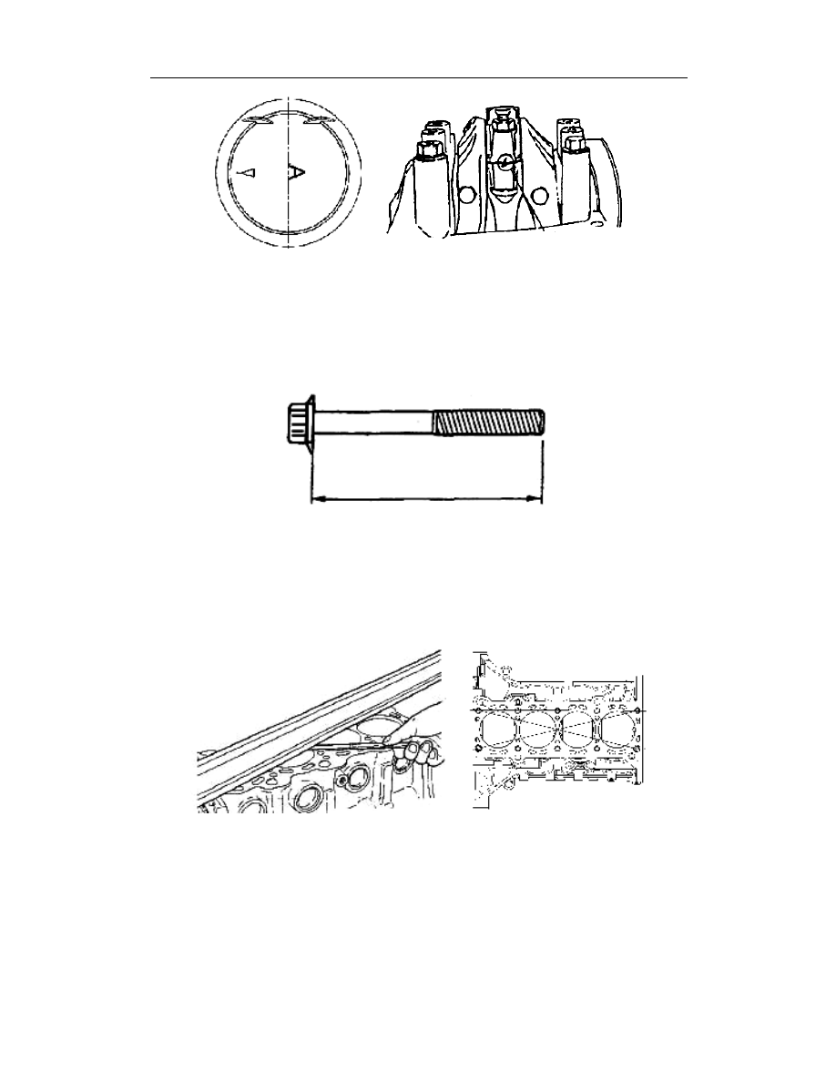
Installation of connecting rod cap  


Measure the length of each bolt. Replace when the standard value exceeded. 


Standard length: 46.7~47.3mm {1.838~1.862in} 


Max.length: 47.6mm {1.874in} 


Check/repair of cylinder block 

1.  Use a straight edge ruler and feeler to measure the distortion on the surface of 

cylinder block as per 6 directions shown in Fig.   

2.  The max.distortion: 0.05mm{0.002in} 


3.  If the distortion on the surface of cylinder block surpassed the max.value, check the 

height of cylinder block. If the height is also out of the standard value, replace the 
cylinder block. 


Standard height: 213.45~213.55mm{8.4035~8.4066in} 

Positioning sign 

Cylinder block and crank connecting rod mechanisms 

76 


4.  If the distortion of cylinder block exceeded the max.value with the height within the 

range of standard value, grind the height or replace the cylinder block. 


Max. grinding size: 0.20mm {0.008in} 

5.  As shown in the following figure, measure the I/D of cylinder with an I/D dial gauge   

at 37mm{1.45in} away from the surface, in the directions of X and Y, . 


6.  If the I/D of cylinder exceeded the wear limit, replace the cylinder block or rebore the 

cylinder and fit the oversized piston to have it conform to the standard clearance of 
between the piston and cylinder. 


Wear limit: 0.15mm {0.006in} 

Attention 

l  The diameter of cylinder boring shall be determined according to the 

oversized diameter of piston. All cylinders shall be in the same diameter. 

l  In order to prevent the heat generation at the time of boring, resulting in 

distortion of cylinder block, the cylinders shall be bored in the following 
order: 2

→4→1→3. 

l  A honing margin of 0.02mm {0.000787in} shall be reserved by boring. After 

the boring, hone the cylinder bore until the last process size. 


Upper face of cylinder block 

Cylinder block and crank connecting rod mechanisms 

77 

I/D of cylinder mm{in} 

Size 

Diameter 

Standard 

84~84.03{3.3071~3.3083} 

Oversize: 0.25{0.01} 

84.25~84.28{3.3169~3.3181} 

Oversize: 0.50{0.02} 

84.50~84.53{3.3268 3.3280} 


Check of piston, piston ring and piston pin  

1.  Measure the piston diameter in the direction perpendicular to the axis of the piston 

pin hole and 28mm {1.10in} below the lower edge of oil ring groove. 

Piston diameter mm {in} 

Size 

Diameter 

standard 

83.97~84{3.3059~3.3071} 

Oversize: 0.25{0.01} 

84.22~84.25{3.3157~3.3169} 

Oversize: 0.50{0.02} 

84.47~84.50{3.3256~3.3268} 


2.  Calculate the clearance between the piston and cylinder. Replace the piston or 

rebore the cylinder when necessary to be applicable to the oversized piston. 


Standard clearance: 0.02~0.04mm{0.000~0.0016in} 


Max.clearance: 0.10mm {0.004in} 

3.  If the piston replaced, the replacement of piston ring shall be also done. 

4.  Measure, with a feeler, the clearance on the entire perimeter between the piston ring 

and ring groove (as shown in Fig.) Replace the piston and piston ring when 
necessary. 


Standard clearance: 


1

st

 ring: 0.030~0.070mm{0.0012~0.0028in} 


2

nd

 ring: 0.020~0.060mm{0.0008~0.0024in} 


Oil ring: 0.040~0.12mm{0.0016~0.047in} 


Max.clearance 


1

st

 and 2

nd

 rings: 0.15mm{0.006in}; Oil ring: 0.15mm {0.006in} 

Cylinder block and crank connecting rod mechanisms 

78 


5.  Place manually the piston ring into the cylinder, use the piston to push the piston ring 

to the stroke end of cylinder bore. 

6.  Measure, with a feeler, the gap of each piston ring. Replace the piston ring when 

necessary. 


Standard notch clearance 


1

st

 ring: 0.20~0.35mm{0.008~0.014in} 


2

nd

 ring: 0.30~0.45mm{0.012~0.018in} 


Oil ring: 0.20~0.50mm{0.008~0.020in} 


Max.gap: 1.0mm{0.039in} 


7.  As shown in Fig., measure the diameter of each piston pin hole at 4 points as A, B, C 

and D in the directions of X and Y. 


Standard diameter: 19.010~19.015mm{0.7484~0.7486in} 


8.  As shown in Fig., measure the diameter of each piston pin at 4 points as A, B, C and 

D in the directions of X and Y. 


Standard diameter: 19.002~19.005mm{0.7481~0.7482in} 


Content   ..  19  20  21  22   ..