HM484Q Engine. Manual - part 20


  Index      FAW     HM484Q Engine (Haima 7) - service manual


Search            


Content   ..  18  19  20  21   ..


HM484Q Engine. Manual - part 20


Cylinder block and crank connecting rod mechanisms 

71 

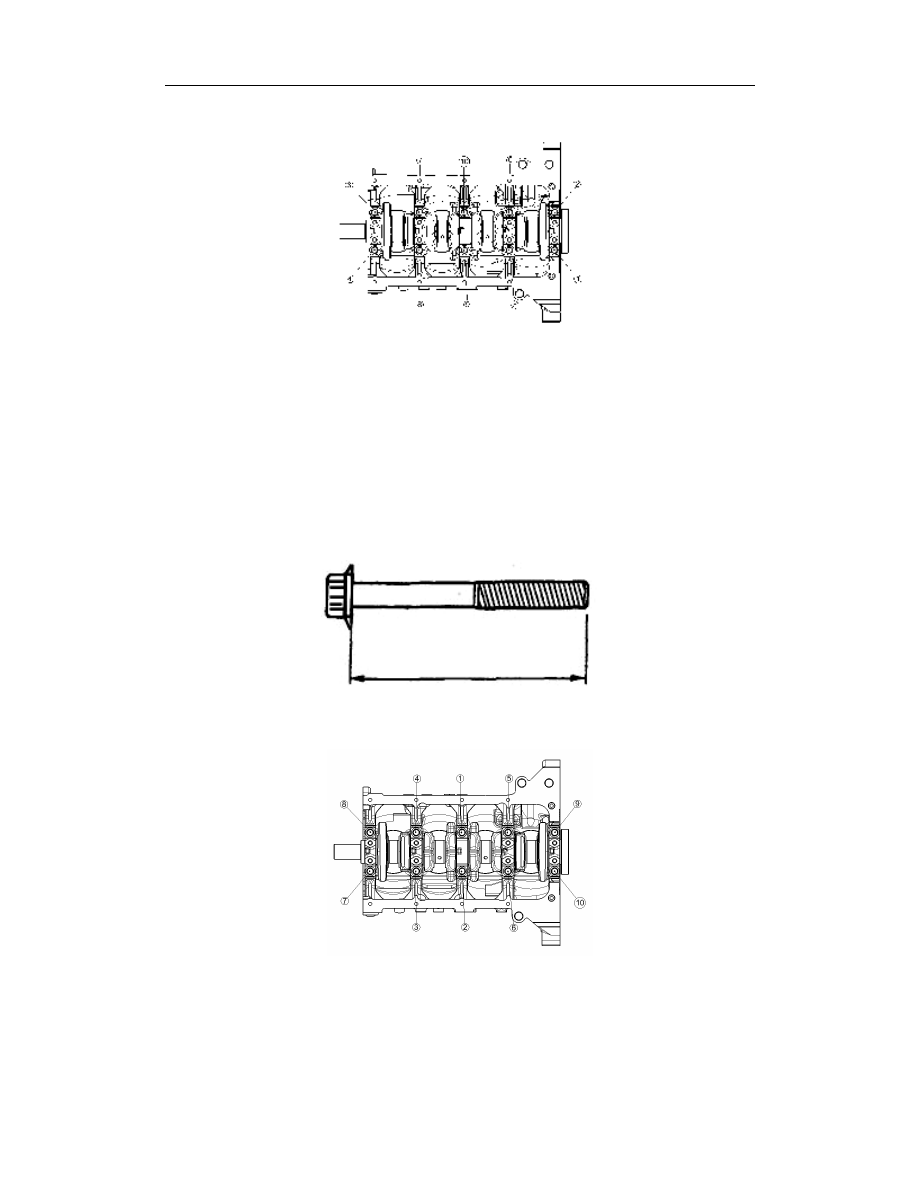
2.  As shown in Fig., unscrew the main bearing cap bolt in several steps. 


Disassembly of crankshaft 

Check the main journal clearance (See

——this section, Check/Repair of Crankshaft). 


Installation of main bearing cap 

1.  Measure the length of each bolt. Replace when the standard value is exceeded. 


Standard length: 67.7~68.3mm {2.665~2.689in} 


Max.length: 68.7mm {2.705in} 


2.  Tighten the bolts in several steps as per the order shown in Fig. 


Cylinder block and crank connecting rod mechanisms 

72 

Installation of piston pin 

1.  Fit the special tool as shown in Fig. 


2.  Insert the special tool no.2 into the piston pin and tighten it on the special tool no.1 


3.  Measure the guide portion length L

2

 of the tool no.2, and calculate as per the 

following formula: L=L

2

-1.75mm; fit the special tools(stop bolt) to make the size L 

suitable. 


4.  Smear clean engine oil on the piston pin. 

5.  Place the piston and connecting rod on the press table, facing upward the 

“F” mark of 

piston side and the 

“HM20” mark side of connecting rod, just as shown in the 

following figure. 


Piston pin 

assembling tools 

Screw 

Stop bolt 

Mark 

“F”of piston side 

“HM20” mark side of connecting rod 

Piston pin assembling tools 

Piston pin assembling tools 

Piston pin 

assembling tools 

Piston pin 

assembling tools 

Guide apparatus 

Piston pin 

assembling tools 

Cylinder block and crank connecting rod mechanisms 

73 

6.  Insert the piston pin and the special tool fitted as per the 2

nd

 step into the piston and 

connecting rod as shown in Fig.,below; 


7.  Use a press to press in the piston pin into the piston and connecting rod until the 

special tool no.2 (guide tube) gets in contact with the special tool (stop bolt). 

8.  While pressing in the piston pin, check the press-in pressure. If lower than the index, 

replace the piston pin or connecting rod. 


Pressure: 4.90~14.70kN(500~1500kgf, 1100~3300lbf) 


9.  Check the pressed depth of piston pin. If it is out of the standard value, restart from 

the 1

st

 step. 


Press-in depth of piston pin: 1.65~2.05mm{0.0650~0.0807in} 


Special tool No.1 

Piston pin assembling tool 

Mark 

“F” of 

piston side 

Press-in depth of piston pin 

Piston pin 

Piston 

Connecting 

rod 

Guide apparatus 

The press-in 

direction is the mark 

“F” of piston side 

Piston pin assembling tool 

Piston pin assembling tool 

Piston pin 

Mark 

“F” of piston side 

Special tool No.2 

Cylinder block and crank connecting rod mechanisms 

74 

Installation of piston ring 

1.  As shown in Fig., below, contain the corrugated ring into the groove of piston ring, 

and then contain one end of the oil control ring into the groove, and then press in 
other parts in place. Afterward, check whether all rings can slide smoothly in both 
directions. 

Caution 

l  Do not use the piston ring expander to fit the oil control ring, otherwise it 

will result in breakage. 


2.  Use a piston ring extender to fit the 2

nd

 and 1

st

 piston control rings. Face the mark 

upward at the time of installation 


3.  Align with the notch of each ring as per the figure below. 


Installation of piston connecting rod assembly 

1.    The arrow on the top of piston aims to the front of engine. 

2.  When the connecting rod cap is fitted, the positioning sign of connecting rod cap shall 

be aligned. 

Head face of oil control ring 

Piston ring extender 

Notch of upper oil control ring 

Notch of lower oil control ring 

Notch of the 2

nd

 ring 

Notch of the 1

st

 ring 

Opening of corrugated ring 

Piston pin 


Content   ..  18  19  20  21   ..