HM484Q Engine. Manual - part 22


  Index      FAW     HM484Q Engine (Haima 7) - service manual


Search            


Content   ..  20  21  22 


HM484Q Engine. Manual - part 22


Cylinder block and crank connecting rod mechanisms 

79 


9.  Calculate the clearance between the piston pin and piston pin hole. Replace the 

piston and / or piston pin when necessary. 


Standard clearance: 0.005~0.013mm{0.0002~0.0005in} 

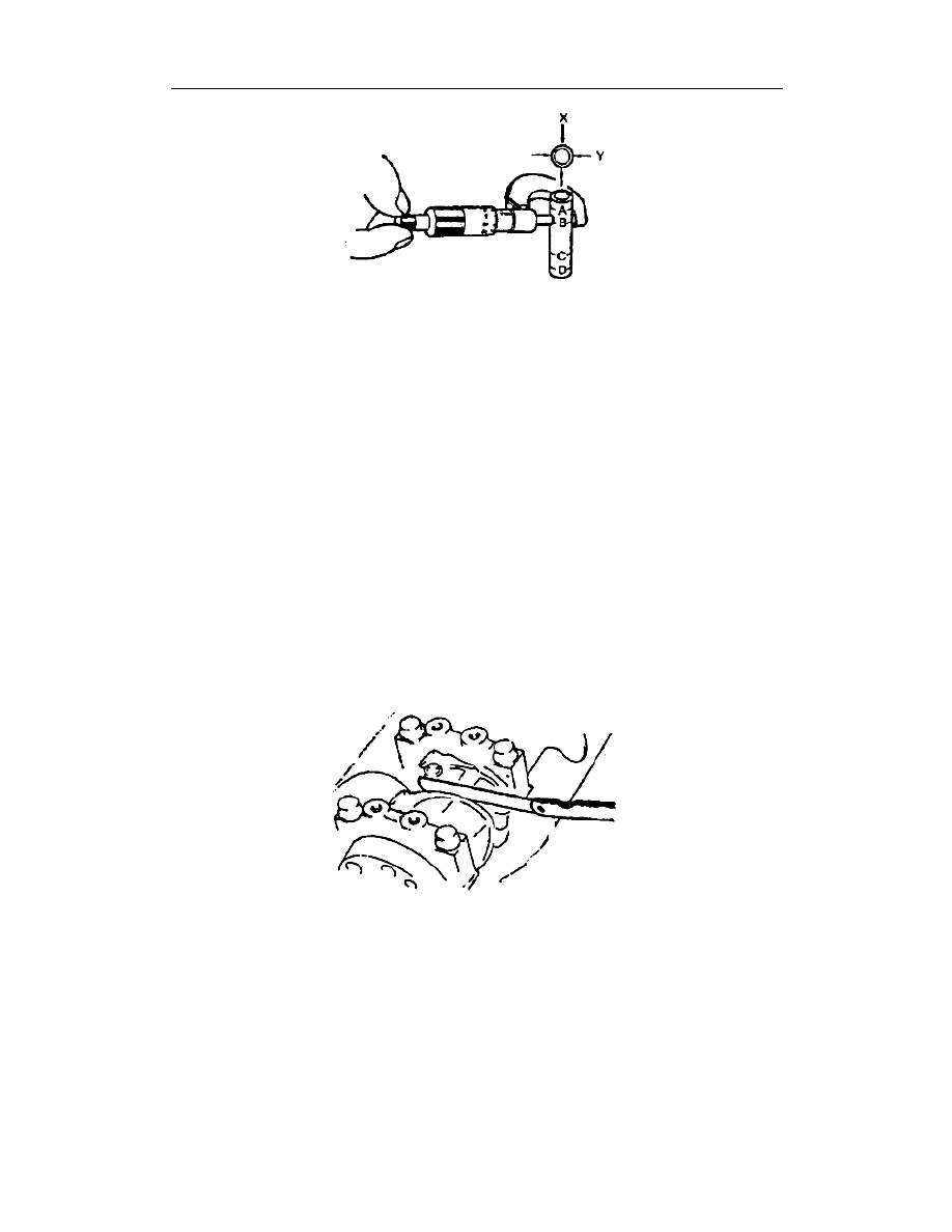
10.  Measure the diameter of connecting rod small end (See

——Check of Connecting 

Rod), calculate the clearance between the connecting rod small end and piston pin. 
Replace the connecting rod or piston pin when necessary. 


Standard clearance: -0.031~-0.017mm{-0.0013~-0.0007in} 


Check of connecting rod 

1.  Measure, with a feeler, the end gap of connecting rod. Replace the connecting rod 

and connecting rod cap when necessary. 


Standard clearance 


0.100~0.250mm {0.004~0.010in} 


Max.clearance 


0.30mm {0.012in} 


2.  Measure the clearance of crankshaft pin journal by the following way: 

(1)   Wipe out all oil on/in the journal and bearing seat; 

(2)   Cut the clearance gauge of plastic line so that it can match with the width of bearing, 

and then place it on the top of journal and perpendicular to its axis. 

(3)   Fit the connecting rod cap (See

——this section, Assembly of Piston and Connecting 

Rod). 

(4)   Remove the connecting rod cap bolt and slowly take out the connecting rod cap. 

(5)   Measure, with a clearance gauge of plastic line, the widest point of extruded part of 

Cylinder block and crank connecting rod mechanisms 

80 

clearance gauge of plastic line, whereby the journal clearance will be achieved. If the 
clearance exceeded the max., value, replace the connecting rod bearing or grind the 
crankshaft pin, and use the bearing applicable to the reduced size of crankshaft pin to 
meet the standard clearance.   


Standard clearance: 0.015~0.048mm{0.0006~0.00191in} 


Max.clearance: 0.10mm {0.0039in} 

mm{in} 

Size of connecting rod bearing 

Thickness of connecting rod bearing 

Standard   

1.487~1.499{0.05854~0.05902} 

0.25{0.01}Oversize: 

1.612~1.624{0.06346~0.06394} 

0.50{0.02}Oversize: 

1.737~1.749{0.06839~0.06886} 


3.  As shown in Fig., measure the I/D of each connecting rod small end in the directions 

X and Y. 


Standard diameter: 18.974~18.985mm{0.7476~0.7474in} 


Check of piston and connecting rod 

As shown in Fig., check the swing torque. If the large end cannot drop in reliance on the 
weight of its own, replace the piston or piston pin. 


Cylinder block and crank connecting rod mechanisms 

81 

Check/repair of crankshaft  

1.  As shown in the following Fig., fit the dial gauge, push forward/rearward the 

crankshaft from its back, measure the end gap of crankshaft. If the end gap exceeded 
the max. value, replace the stop bearing or grind the crankshaft, and fit the bearing 
applicable to the reduced size of crankshaft to meet the standard end gap. 


Standard end gap: 0.05~0.25mm{0.002~0.011in} 


Max. end gap: 0.30mm{0.012in} 

mm{in} 

Size of stop bearing 

Thickness of stop bearing 

Standard   

1.925~1.975{0.0758~0.0778} 

Reduced size of 0.25{0.01} 

2.05~2.100{0.0807~0.0827} 

Reduced size of 0.50{0.02} 

2.175~2.225{0.0856~0.0876} 

Reduced size of 0.75{0.03} 

2.300~2.350{0.0906~0.0925} 


2.  Measure the radius run-out of crankshaft. Replace the crankshaft when necessary. 


Max. radical run-out: 0.03mm{0.0012in} 


3.  At two points of A and B shown in Fig., measure the journal diameter in the directions 

X and Y. replace the crankshaft or grind the journal when necessary and fit the 
bearing applicable to the reduced size of crankshaft. 

mm{in} 

Main journal 

Diameter 

Standard 

49.982~50{1.9678~1.9685} 

Reduce size: 0.25{0.01} 

49.732~49.75{1.9580~1.9586 

Cylinder block and crank connecting rod mechanisms 

82 

mm{in} 

Crank pin 

Diameter 

Standard   

44.980~45.000{1.7709~1.7717} 

Reduce size: 0.25{0.01} 

44.730~44.750{1.7610~1.7618} 

Reduce size: 0.50{0.02} 

44.480~44.500{1.7512~1.7520} 


4.  Measure the main journal clearance in the following way. 

(1)  Wipe out the oil on/in the crankshaft journal and bearing seat. 

(2)  Cut the clearance gauge of plastic line so that it can match with the bearing width and 

then place it on the top of journal and perpendicular to its axis. 

(3)  Fit the main bearing cap (See

——this section, Installation of Main Bearing Cap). 

(4)  Remove the main bearing cap bolt and slowly take out the main bearing cap 

(See

——this section, Installation of Main Bearing Cap). 

(5)  Measure, with a clearance gauge of plastic line, the widest point of extruded part of 

clearance gauge of plastic line, whereby the journal clearance can be achieved. If the 
clearance exceeded the max. value, grind the main bearing hole and fit the bearing 
suitable for the reduced size of crankshaft to meet the current clearance. 


Standard clearance: 0.018~0.036mm{0.00071~0.00142in} 


Max.clearance: 0.1mm {0.0039in} 

mm{in} 

Size of bearing 

Thickness of bearing 

Standard 

1.988~2.003{0.0783~0.0789} 

Reduced size: 0.25{0.01} 

2.113~2.128{0.0831~0.0837} 


Content   ..  20  21  22