HM484Q Engine. Manual - part 17


  Index      FAW     HM484Q Engine (Haima 7) - service manual


Search            


Content   ..  15  16  17  18   ..


HM484Q Engine. Manual - part 17


Cylinder head and valve mechanisms 

59 

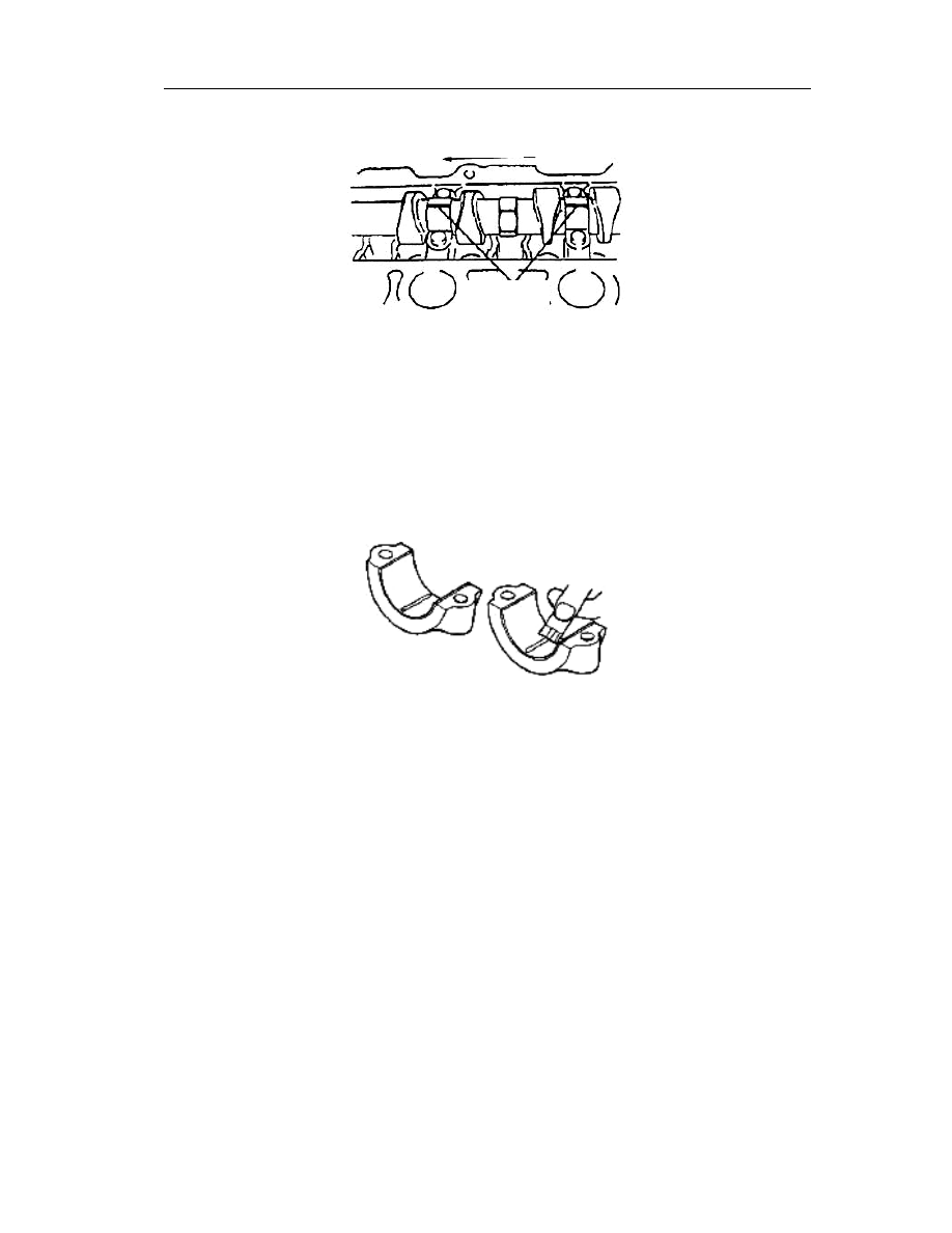
matching with the bearing width, and then place it on the journal in the axis direction. 


(4)  Fit the camshaft cover (See

——Removal/Installation of Cylinder Head, Precautions to the 

Installation of Camshaft). 


Attention: Do not turn the camshaft while measuring the clearance. 

(5)  Disassemble the camshaft cover (See

——Removal/Installation of Cylinder Head, 

Precautions to the Disassembly of Camshaft). 

(6)  Measure the widest point of extruded part of clearance gauge of plastic line by use of the 

scale on the clearance gauge of plastic line, resulting therefore in the journal clearance. 
Replace the cylinder head and camshaft cover when necessary. 


Standard journal clearance: 0.035~0.081mm{0.0014~0.0031in} 


5.  Fit the camshaft cover (See

——Removal/Installation of Cylinder Head, Precautions to the 

Disassembly of Camshaft). 

6.  As shown in the following Fig., fit the dial gauge, push forward/rearward the camshaft from 

its back, measure the end gap of camshaft. Replace the cylinder head or camshaft when 
necessary. 

Caution 

l  Do not push the camshaft with the cam so to prevent damage of cam. 


Standard end gap: 0.08~0.20mm{0.0031~0.0078in} 


Max. end gap: 0.21mm {0.0082in} 


Check of tappet  

1.  Measure the diameter of each tappet hole at two points of A and B shown in Fig, 

respectively in the directions X and Y, replace the camshaft when necessary. 


Standard diameter: 31.000~31.025mm{1.2205~1.2215in} 

Clearance gauge 

of plastic line 

Axis direction 

Cylinder head and valve mechanisms 

60 


2.  Measure the diameter of each tappet hole at two points of 

A and B shown in Fig, respectively in the directions X and 
Y.   


Standard diameter: 30.964~30.980mm{1.2191~
1.2197in} 


3.  Calculate the clearance between the tappet and appropriate tappet hole. Replace the 

tappet or cylinder head if necessary 


Standard clearance: 0.020~0.061mm{0.00079~0.00240in} 


Max. clearance: 0.180mm {0.0071in} 


Flywheel and clutch 

61 

Flywheel and clutch 

Removal/installation of flywheel and clutch 

1.  If necessary to disassemble the crankshaft rear cover, the oil pan body shall be removed at 

first (See

——Lubrication System, Disassembly/Assembly of Oil Pan Body). 

2.  Disassemble as per the order shown in Fig. 

3.  Assemble in the reversing order of disassembly. 


Clutch compressing disc (See

——Disassembly Instructions /See——Assembly 

instructions) 

Clutch disc plate(See

——Disassembly Instructions /See——Assembly instructions) 

Flywheel (See

——Disassembly Instructions /See——Assembly instructions) 

Pilot bearing(See

——Disassembly Instructions /See——Assembly instructions) 

Crankshaft rear cover(See

——Disassembly Instructions of Rear Oil Seal 

/See

——Assembly instructions of Rear Oil Seal /See——Assembly instructions) 

Gearbox partition   

Disassembly instructions of clutch compressing disc and disc plate 

1.  Use a special tool to lock the flywheel and localize the clutch (as shown in Fig.). 

2.  Unscrew the bolts by one time, as per the criss cross method, until the pressure of 

diaphragm spring has been released. 

3.  Remove the clutch compressing disc and disc plate. 

Smear prior to 
the installation 

Special tools for 

disassembly and assembly 

Part 

replacement is 

necessary after 

removal 

Part replacement is 

necessary after removal 

Sealant coating is 

necessary after the 

rear cover installation Sealant coating is 

necessary after the 

rear cover installation 

Sealant coating is necessary 

after the rear cover installation 

Sealant coating is necessary 

after the rear cover installation 

Flywheel and clutch 

62 


Disassembly instructions of flywheel 

1.  Use a special tool (as shown in Fig.) to clamp the flywheel. 

2.  Dismantle evenly the mounting bolts in several times according to the criss cross order (as 

shown in Fig.)   

3.  Remove the flywheel. 


Disassembly instructions of pilot bearing 

Attention 

l  In general, it is unnecessary to disassemble the pilot bearing other than 

replacement. 

Use a special tools (as shown in Fig.) to disassemble the pilot bearing. 


Disassembly instructions of rear oil seal  

Attention 

l  In general, it is unnecessary to disassemble the rear oil seal other than 

Gear ring fixture component 

Gear ring fixture component 

Positioning tool of clutch disc 

Needle bearing puller 


Content   ..  15  16  17  18   ..