HM484Q Engine. Manual - part 15


  Index      FAW     HM484Q Engine (Haima 7) - service manual


Search            


Content   ..  13  14  15  16   ..


HM484Q Engine. Manual - part 15


Cylinder head and valve mechanisms 

51 

l  If the valve clearance exceeded the standard value, replace the tappet 

(See

——Adjustment of Valve Clearance). 

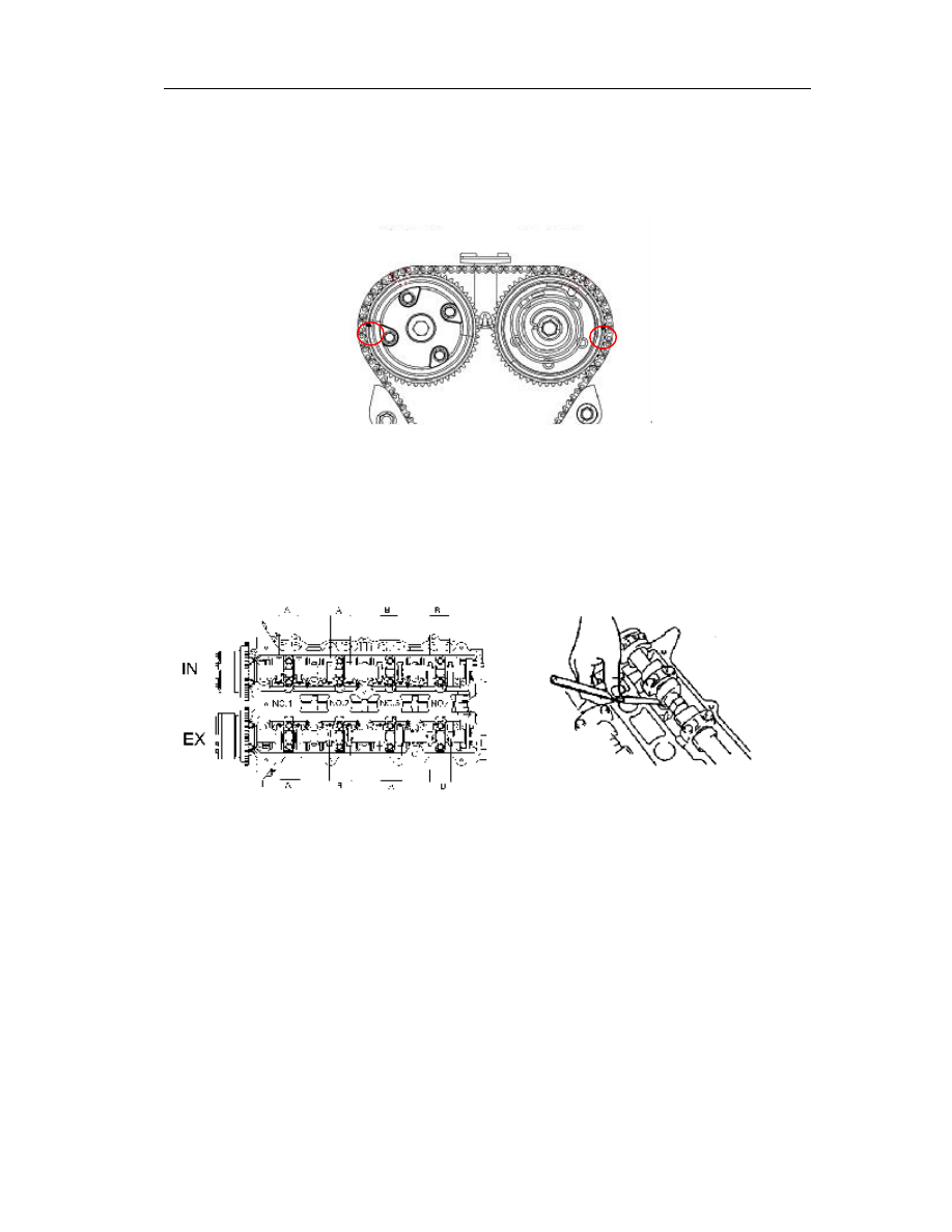
(3)  Turn clockwise the crankshaft for 360

o

, enabling the piston to locate on the TDC of cylinder 

no.4, i.e.: allow the valve check signs on the intake and exhaust VVTs to locate as shown 
in Fig. below. 


(4)  Measure with a feeler the valve clearances of all cylinders as marked in Fig. B. 

l  If the valve clearance exceeded the standard value, replace the tappet 

(See

——Adjustment of Valve Clearance). 


Standard value of valve clearance (the engine under cooling state) 


Intake: 0.18~0.26mm{0.0071~0.0102in}(0.22

±0.04mm{0.0087±0.0016in}) 


Exhaust0.26~0.34mm{0.0102~0.0134in}(0.30

±0.04mm{0.0118±0.0016in}) 


4.  Fit the cylinder head cover (See

——Installation of Timing Sprocket and Cylinder Head 

Cover). 


Adjustment of valve clearance 

All valves which require the adjustment of clearance shall be operated as per the following 
procedure:   

1.  Turn clockwise the camshaft with the key slot of crankshaft facing upward. 

2.  Disassemble the camshaft (See this section, Disassembly of Camshaft). 

3.  Take out the tappet whose valve clearance needs to be adjusted. 

4.  Select a suitable tappet. 


Thickness of new tappet = thickness of old tappet + measured valve clearance-standard 
valve clearance 

Intake side 

Exhaust side 

Cylinder head and valve mechanisms 

52 


(Intake: 0.22mm{0.0087in}; exhaust: 0.30mm{0.0118in}) 

5.  Contain the selected tappet into the tappet hole. 

6.  Reconfirm the valve clearance (See the Valve Clearance, Inspection of Valve Clearance). 

Attention 

l  The thickness of tappet will be marked in 3 digitals at the side of tappet as 

shown in Fig., below. 


Relationship between the tappet mark and thickness is shown in the following table:   

Mark   

Thickness (mm) 


Mark 

Thickness (mm) 


Mark   

Thickness (mm) 

270 

2.70   

292 

2.92   

314 

3.14   

272 

2.72   

294 

2.94   

316 

3.16   

274 

2.74   

296 

2.96   

318 

3.18   

276 

2.76   

298 

2.98   

320 

3.20   

278 

2.78   

300 

3.00   

322 

3.22   

280 

2.80   

302 

3.02   

324 

3.24   

282 

2.82   

304 

3.04   

326 

3.26   

284 

2.84   

306 

3.06   

328 

3.28   

286 

2.86   

308 

3.08   

330 

3.30   

288 

2.88   

310 

3.10   


290 

2.90   

312 

3.12   


Thickness mark 

Cylinder head and valve mechanisms 

53 

Check/repair of cylinder head  

1.  Make a defect test on the cylinder head. Replace the cylinder head when necessary. 

2.  Check the following items and repair or replace as necessary. 

(1)   Whether the valve seat is sunken. 

(2)   Whether the journal and end clearances of camshaft are too large. 

3.  Use a straight edge ruler and feeler as shown in Fig. to check in 6 directions whether the 

cylinder head is distorted. 


Max Distortion: 0.06mm (0.002in) 


4.  If the distortion of cylinder head surpassed the max.value, check the height of cylinder 

head. If the height is also out of the standard value, replace the cylinder head. 


Standard height: 124.45~124.55mm{4.8996~4.9035in} 


5.  If the distortion of cylinder head exceeded the max. value, but the height within the 

standard value, you can grind the height or replace the cylinder head. 


Max.grinding tolerance: 0.20mm (0.0078in) 

6.  Use a straight edge ruler and feeler as shown in Fig. to measure the distortions in all 

directions of manifold flanges of cylinder head intake and exhaust.   


Max. distortion: 0.05mm (0.0019in) 


Cylinder head and valve mechanisms 

54 


7.  If the distortion measured by the 6 step exceeded the max.value, grind the surface or 

replace the cylinder head. 


Max.grinding tolerance: 0.20mm (0.0078in) 


Check of valve and valve guide 

1.  Measure the edge thickness of each valve head and replace the valve when necessary. 


Standard thickness: intake valve: 0.85mm{0.034in}; exhaust valve: 1.50mm {0.059in} 


Min.thickness: exhaust valve: 0.35mm{0.014in}; exhaust valve: 0.90mm {0.035in} 


2.  Measure the length of each valve and replace the valve as necessary. 


Standard length: 


Intake valve: 101.15~101.65{3.9823~4.0020} 


Exhaust valve: 101.07~101.57{3.9791~3.9988} 


Min. length: 


Intake valve: 100.95mm {3.9744in} 


Exhaust valve: 100.87mm {3.9712in} 

3.  Measure the diameter of each valve rod, at three points of A, B and C shown in Fig, 

respectively in the directions X and Y, replace the valve when necessary. 


Standard diameter: 


Intake valve: 4.965~4.980mm{0.1954~0.1961in} 


Exhaust valve: 4.955~4.970mm{0.1951~0.1957in} 


Min.diameter 


Intake valve: 4.915mm {0.1935in} 


Exhaust valve: 4.905mm {0.1931in} 


Thickness of edge 


Content   ..  13  14  15  16   ..