HM484Q Engine. Manual - part 13
Cylinder head and valve mechanisms
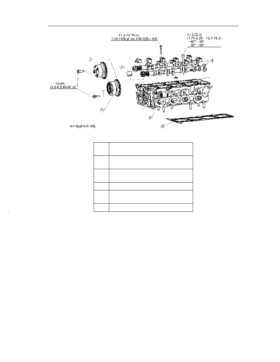
43
1
Intake VVT(please refer to Removal/
Installation Instructions)
2
Exhaust VVT(please refer to Removal/
Installation Instructions)
3
Camshaft (please refer to Removal/
Installation Instructions)
4
Tappet
5
Cylinder head (Removal/Installation
Instructions)
6
Cylinder head pad
错
Smear prior to the
installation
Smear prior to
the installation
Smear prior to
the installation
Smear prior to the
installation of
cylinder head
Part replacement is
necessary after the
disassembly