HM484Q Engine. Manual - part 12


  Index      FAW     HM484Q Engine (Haima 7) - service manual


Search            


Content   ..  10  11  12  13   ..


HM484Q Engine. Manual - part 12


Lubrication system 

39 


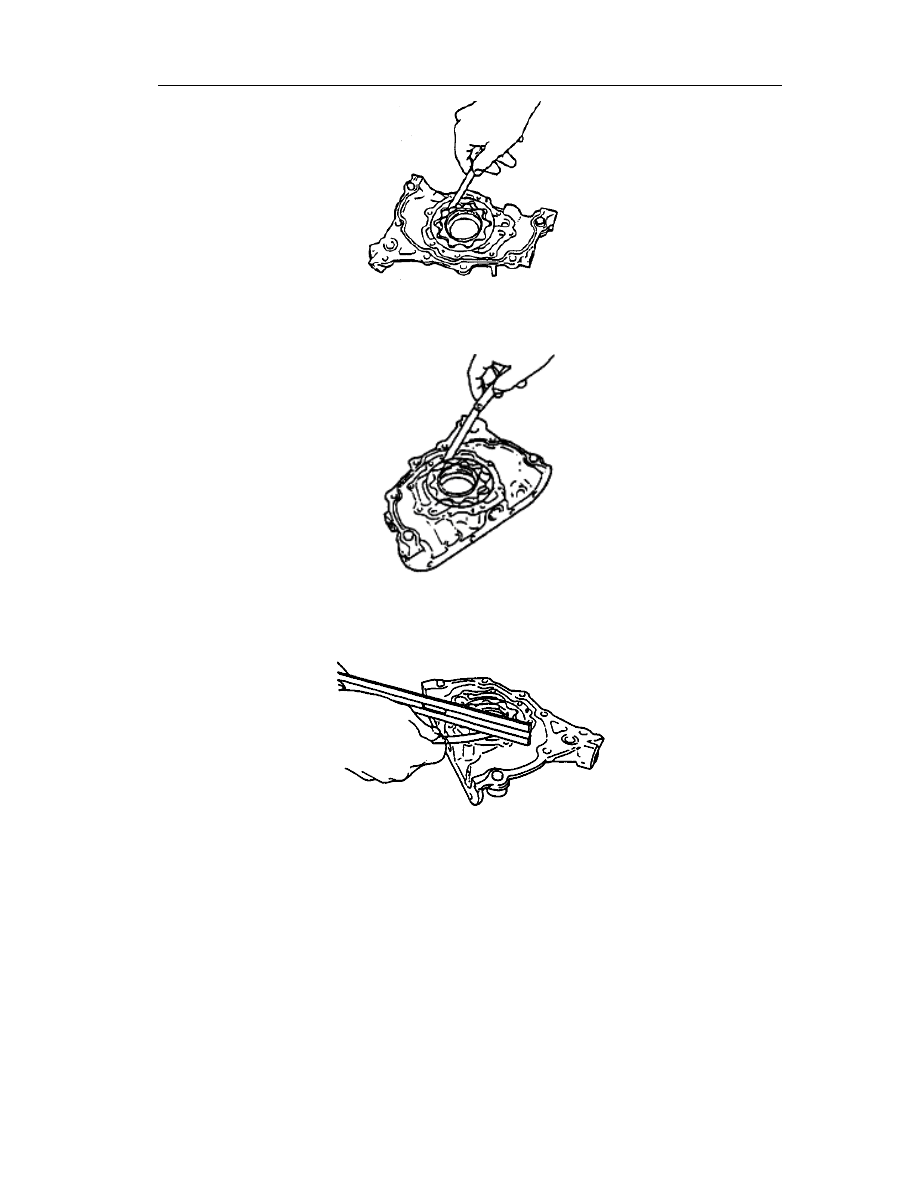
Standard clearance of pump body: 0.100~0.181{0.0040~0.0071} 


Max.clearance of pump body: 0.22mm {0.009in} 


Standard lateral clearance: 0.040~0.095mm{0.0016~0.0037in} 


Max. lateral clearance: 0.14mm {0.055in} 


Lubrication system 

40 

Check of pressure spring   

Apply pressure on the spring and check the 

spring height. Replace the pressure 
spring if necessary. 


Pressure:   


82.6~90.4N{8.43~9.22kgf, 18.56~
20.31lbf} 


Standard height:   


35.15mm [1.3839in] 


Cold system 

Removal/installation of thermostat 

1.  Disassemble as per the order shown in 

Fig. 

2.  Assemble in the reversing order of 

disassembly. 

Thermostat cover 

Thermostat   

See

——Precautions to Installation 


Assembly instructions of thermostat 

1.  As  shown  in  Fig.,  confirm  whether  the  notches  on  the  thermostat  switching  section  and 

thermostat washer have been aligned. 

2.  Align  with  the  notch  on  the  washer,  and  fit  the  thermostat  on  the  thermostat  switching 

section. 


Check of thermostat 

Put  the  thermostat  into  a  vessel  containing  hot  water  and  then  heat  it  up  by  inserting  the 

Bulge 

Mobile pin 

Cylinder head and valve mechanisms 

41 

thermostat in water. Check the thermostat. 

l  If non-conform to the provisions, replace the thermostat. 

—  Close the valve at room temperature. 

—  Warm up and open the valve. 

Items 

Engine 

Initial temperature(℃{℉}) 

80~84{176~183} 

Fully opened temperature(℃{℉}) 

95{203} 

Fully opened stroke(mm{in}) 

≥8.5{0.33} 


Removal/installation of cooling water 
pipe 

1.  Remove the thermostat (See

——this 

section, Disassembly/assembly of 
Thermostat). 

2.  Disassemble as per the order shown in 

Fig. 

3.  Assemble in the reversing order of 

disassembly. 

Bypass pipeline. See

——Assembly 

instructions 

Thermostat switching section 

Outlet pipe seat 


Assembly instructions of cooling water pipe  

Replace the O-ring and then smear water on the O-ring to ease its loading. 

l  Attention: Do not smear the engine oil or other oily substances on the O-ring. 


Part replacement is 

necessary after the 

disassembly 

Part rep lacement is 

necessary after the 

disassembly 

Part replacement is 

necessary after the 

disassembly 

Cylinder head and valve mechanisms 

42 

Removal/installation of water pump   

1.  Remove the engine belt. (See

——Engine 

Belt) 

2.  Disassemble as per the order shown in 

Fig. 

3.  Assemble in the reversing order of 

disassembly. 

Bolt   

Water pump 


Cylinder head and valves 

Removal/installation of cylinder head 

1.  Remove the intake/exhaust manifold (See

——Intake/Exhaust System). 

2.  Remove the timing sprocket (See

——Timing Sprocket). 

3.  Disassembly as shown in Fig. 

4.  Assemble in the reversing order of disassembly. 

Part replacement is 

necessary after the 

disassembly 


Content   ..  10  11  12  13   ..