Dodge Durango (2022 year). Manual in english - page 17
 

  Index      Manuals     Dodge Durango (2022 year). Manual in english


Search            copyright infringement  


Content      ..     15      16      17      18     ..


Dodge Durango (2022 year). Manual in english - page 17


266

SERVICING AND MAINTENANCE


3. Pull the right hand side of the glove 

compartment door toward the rear of the 

vehicle to disengage the glove compartment 

door from its hinges.

NOTE:

When disengaging the glove compartment door 

from its hinges, there will be some resistance.
4. With the glove compartment door loose, 

remove the glove compartment tension tether 

and tether clip by sliding the clip toward the 

face of the glove compartment door and lifting 

the clip out of glove compartment door.

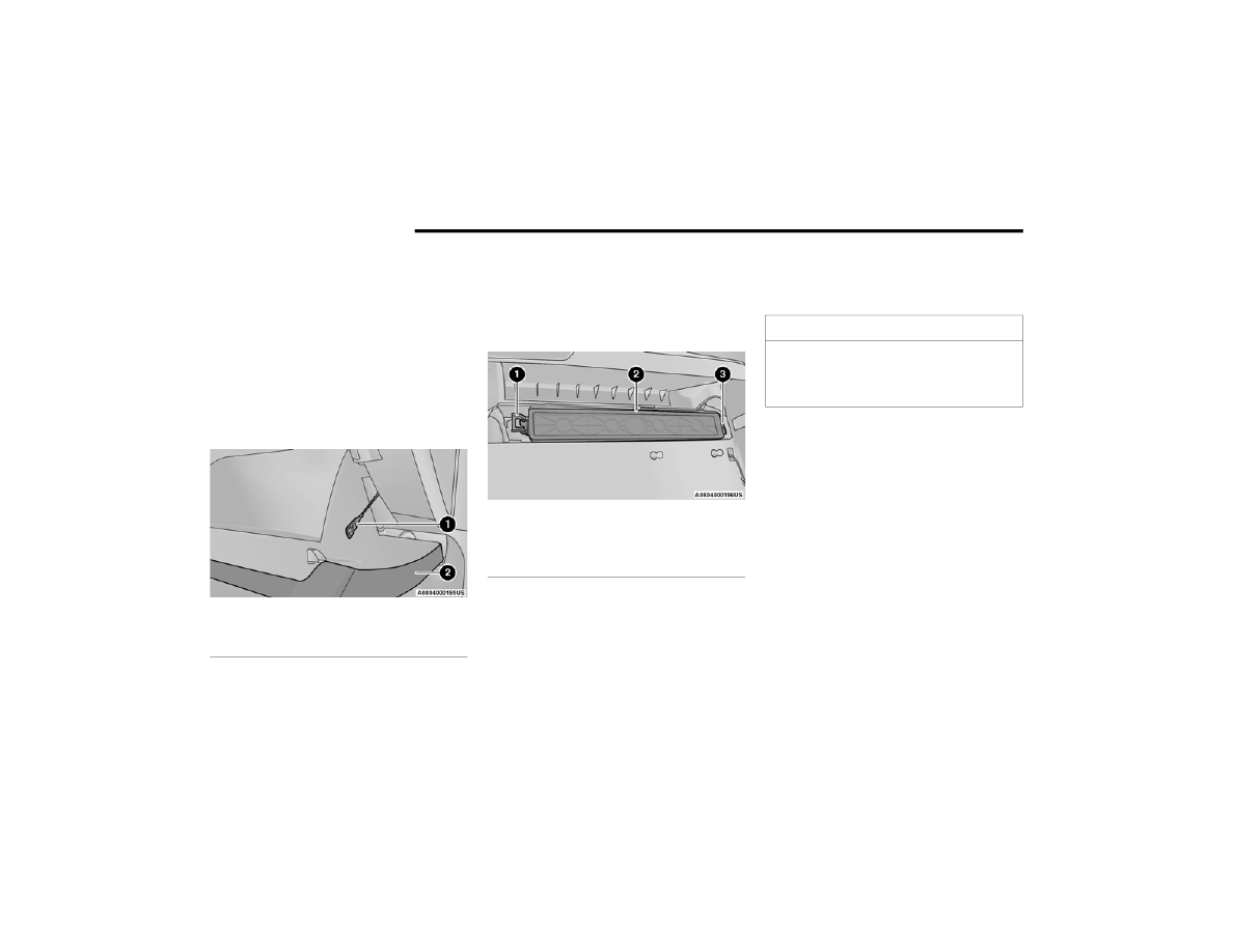
Right Side Of Glove Compartment

5. Remove the filter cover by disengaging the 

retaining tab and mid way snap that secures 

the filter cover to the HVAC housing. Disengage 

the mid way snap by pulling the door outward. 

Unhinge the filter cover on the right side to fully 

remove the cover.

Cabin Air Filter Cover

6. Remove the cabin air filter by pulling it straight 

out of the housing.

7. Install the cabin air filter with the arrow on the 

filter pointing toward the floor. When installing 

the filter cover, make sure the retaining tabs 

fully engage the cover.

8. Reinstall the glove compartment door on the 

door hinge and reattach the tension tether by 

inserting the tether clip in the glove 

compartment and sliding the clip away from 

the face of the glove compartment door.

9. Push the door to the near closed position to 

reengage the glove compartment travel stops.

NOTE:

Ensure the glove compartment door hinges and 

glove compartment travel stops are fully engaged.

1 — Glove Compartment Tension Tether
2 — Glove Compartment Door

1 — Retaining Tab
2 — Mid Way Snap
3 — Filter Cover Hinge

CAUTION!

The cabin air filter is identified with an arrow to 

indicate airflow direction through the filter. 

Failure to properly install the filter will result in 

the need to replace it more often.

SERVICING AND MAINTENANCE

267

A

CCESSORY

 D

RIVE

 B

ELT

 I

NSPECTION

When inspecting accessory drive belts, small 

cracks that run across the ribbed surface of the 

belt from rib to rib, are considered normal. This is 

not a reason to replace belt. However, cracks 

running along a rib (not across) are not normal. 

Any belt with cracks running along a rib must be 

replaced. Also have the belt replaced if it has 

excessive wear, frayed cords or severe glazing.

Accessory Belt (Serpentine Belt)

Conditions that would require replacement:

Rib chunking (one or more ribs has separated 

from belt body)

Rib or belt wear

Longitudinal belt cracking (cracks between two 

ribs)

Belt slips

Groove jumping (belt does not maintain correct 

position on pulley)

Belt broken (identify and correct problem before 

new belt is installed)

Noise (objectionable squeal, squeak, or rumble 

is heard or felt while drive belt is in operation)

Some conditions can be caused by a faulty 

component such as a belt pulley. Belt pulleys 

should be carefully inspected for damage and 

proper alignment.
Belt replacement on some models requires the 

use of special tools. We recommend having your 

vehicle serviced at an authorized dealer.

B

ODY

 L

UBRICATION


Locks and all body pivot points, including such 

items as seat tracks, door hinge pivot points and 

rollers, liftgate, tailgate, decklid, sliding doors and 

hood hinges, should be lubricated periodically. Use 

a lithium-based grease, such as Mopar® Spray 

White Lube to ensure quiet, easy operation and to 

protect against rust and wear. Prior to the 

application of any lubricant, the parts concerned 

should be wiped clean to remove dust and grit; 

after lubricating excess oil and grease should be 

removed. Particular attention should also be given 

to hood latching components to ensure proper 

function. When performing other underhood 

services, the hood latch, release mechanism and 

safety catch should be cleaned and lubricated.
The external lock cylinders should be lubricated 

twice a year, preferably in the Autumn and Spring. 

Apply a small amount of a high quality lubricant, 

such as Mopar® Lock Cylinder Lubricant directly 

into the lock cylinder.

WARNING!

Do not attempt to inspect an accessory drive 

belt with vehicle running.

When working near the radiator cooling fan, 

disconnect the fan motor lead. The fan is 

temperature controlled and can start at any 

time regardless of ignition mode. You could be 

injured by the moving fan blades.

You can be badly injured working on or around 

a motor vehicle. Only do service work for which 

you have the knowledge and the proper equip

-

ment. If you have any doubt about your ability 

to perform a service job, take your vehicle to a 

competent mechanic.

8

268

SERVICING AND MAINTENANCE


W

INDSHIELD

 W

IPER

 B

LADES


Clean the rubber edges of the wiper blades and the 

windshield periodically with a sponge or soft cloth 

and a mild nonabrasive cleaner. This will remove 

accumulations of salt or road film.
Operation of the wipers on dry glass for long 

periods may cause deterioration of the wiper 

blades. Always use washer fluid when using the 

wipers to remove salt or dirt from a dry windshield.
Avoid using the wiper blades to remove frost or ice 

from the windshield. Keep the blade rubber out of 

contact with petroleum products such as engine 

oil, gasoline, etc.
NOTE:

Life expectancy of wiper blades varies depending 

on geographical area and frequency of use. If chat

-

tering, marks, water lines or wet spots are present, 

clean the wiper blades or replace as necessary.
The wiper blades and wiper arms should be 

inspected periodically, not just when wiper 

performance problems are experienced. This 

inspection should include the following points:

Wear or uneven edges

Foreign material

Hardening or cracking

Deformation or fatigue

If a wiper blade or wiper arm is damaged, replace 

the affected wiper arm or blade with a new unit. Do 

not attempt to repair a wiper arm or blade that is 

damaged.

Front Wiper Blade Removal/Installation

1. Lift the wiper arm to raise the wiper blade off 

of the glass, until the wiper arm is in the full 

up position.

Wiper Blade With Release Tab In Locked Position

2. To disengage the wiper blade from the wiper 

arm, flip up the release tab on the wiper blade 

and while holding the wiper arm with one 

hand, slide the wiper blade down towards the 

base of the wiper arm.

Wiper Blade With Release Tab In Unlocked Position

CAUTION!

Do not allow the wiper arm to spring back 

against the glass without the wiper blade in 

place or the glass may be damaged.

1 — Wiper
2 — Release Tab
3 — Wiper Arm

1 — Wiper Blade
2 — Release Tab
3 — Wiper Arm

SERVICING AND MAINTENANCE

269

3. With the wiper blade disengaged, remove the 

wiper blade from the wiper arm by holding the 

wiper arm with one hand and separating the 

wiper blade from the wiper arm with the other 

hand (move the wiper blade toward the right 

side of the vehicle to separate the wiper blade 

from the wiper arm).

Wiper Blade Removed From Wiper Arm

4. Gently lower the wiper arm onto the glass.

Installing The Front Wipers
1. Lift the wiper arm off of the glass, until the 

wiper arm is in the full up position.

2. Position the wiper blade near the hook on the 

tip of the wiper arm with the wiper release tab 

open and the blade side of the wiper facing up 

and away from the windshield.

3. Insert the hook on the tip of the arm through 

the opening in the wiper blade under the 

release tab.

4. Slide the wiper blade up into the hook on the 

wiper arm and rotate the wiper blade until it is 

flush against the wiper arm. Fold down the 

latch release tab and snap it into its locked 

position. Latch engagement will be 

accompanied by an audible click.

5. Gently lower the wiper blade onto the glass.

Rear Wiper Blade Removal/Installation

1. Lift the rear wiper arm pivot cap away from 

the glass to allow the rear wiper blade to be 

raised off of the glass.

NOTE:

The rear wiper arm cannot be fully raised off the 

glass unless the wiper arm pivot cap is unsnapped 

first. Attempting to fully raise the rear wiper arm 

without unsnapping the wiper arm pivot cap may 

damage the vehicle.

Wiper Pivot Cap In Unlocked Position

1 — Wiper Blade
2 — Release Tab
3 — Wiper Arm

1 — Wiper Arm Pivot Cap
2 — Wiper Arm

8

270

SERVICING AND MAINTENANCE


2. Lift the rear wiper arm fully off the glass.

Wiper Blade In Folded Out Position

3. To remove the wiper blade from the wiper arm, 

grasp the bottom end of the wiper blade 

nearest to wiper arm with your right hand. With 

your left hand hold the wiper arm as you pull 

the wiper blade away from the wiper arm past 

its stop far enough to unsnap the wiper blade 

pivot pin from the receptacle on the end of the 

wiper arm.

NOTE:

Resistance will be accompanied by an audible 

snap.
4. Still grasping the bottom end of the wiper 

blade, move the wiper blade upward and away 

from the wiper arm to disengage.

Wiper Blade Removed From Wiper Arm

5. Gently lower the tip of the wiper arm onto the 

glass.

Installing The Rear Wiper
1. Lift the rear wiper arm pivot cap away from 

the glass to allow the rear wiper blade to be 

raised off of the glass.

NOTE:

The rear wiper arm cannot be fully raised off the 

glass unless the wiper arm pivot cap is unsnapped 

first. Attempting to fully raise the rear wiper arm 

without unsnapping the wiper arm pivot cap may 

damage the vehicle.
2. Lift the rear wiper arm fully off the glass.
3. Insert the wiper blade pivot pin into the 

opening on the end of the wiper arm. Grab the 

bottom end of the wiper arm with one hand, 

and press the wiper blade flush with the wiper 

arm until it snaps into place.

4. Lower the wiper blade onto the glass and snap 

the wiper arm pivot cap back into place.

1 — Wiper Blade
2 — Wiper Arm
3 — Wiper Arm Pivot Cap

1 — Wiper Blade
2 — Wiper Blade Pivot Pin
3 — Wiper Arm Receptacle
4 — Wiper Arm

SERVICING AND MAINTENANCE

271

(Continued)

E

XHAUST

 S

YSTEM


The best protection against carbon monoxide entry 

into the vehicle body is a properly maintained 

engine exhaust system.
If you notice a change in the sound of the exhaust 

system; or if the exhaust fumes can be detected 

inside the vehicle; or when the underside or rear of 

the vehicle is damaged; have an authorized 

technician inspect the complete exhaust system 

and adjacent body areas for broken, damaged, 

deteriorated, or mispositioned parts. Open seams 

or loose connections could permit exhaust fumes 

to seep into the passenger compartment. In 

addition, have the exhaust system inspected each 

time the vehicle is raised for lubrication or oil 

change. Replace as required.

Under normal operating conditions, the catalytic 

converter will not require maintenance. However, it 

is important to keep the engine properly tuned to 

ensure proper catalyst operation and prevent 

possible catalyst damage.
NOTE:

Intentional tampering with emissions control 

systems can result in civil penalties being 

assessed against you.
In unusual situations involving grossly 

malfunctioning engine operation, a scorching odor 

may suggest severe and abnormal catalyst 

overheating. If this occurs, stop the vehicle, turn off 

the engine and allow it to cool. Service, including a 

tune-up to the manufacturer's specifications, 

should be obtained immediately.
To minimize the possibility of catalytic converter 

damage:

Do not interrupt the ignition when the transmis

-

sion is in gear and the vehicle is in motion.

Do not try to start the vehicle by pushing or 

towing the vehicle.

Do not idle the engine with any ignition compo

-

nents disconnected or removed, such as when 

diagnostic testing, or for prolonged periods 

during very rough idle or malfunctioning oper

-

ating conditions.

WARNING!

Exhaust gases can injure or kill. They contain 

Carbon Monoxide (CO), which is colorless and 

odorless. Breathing it can make you uncon

-

scious and can eventually poison you. 

To avoid breathing CO see  

Ú

page 231.

A hot exhaust system can start a fire if you 

park over materials that can burn. Such mate

-

rials might be grass or leaves coming into 

contact with your exhaust system. Do not park 

or operate your vehicle in areas where your 

exhaust system can contact anything that

can burn.

CAUTION!

The catalytic converter requires the use of 

unleaded fuel only. Leaded gasoline will 

destroy the effectiveness of the catalyst as an 

emissions control device and may seriously 

reduce engine performance and cause 

serious damage to the engine.

Damage to the catalytic converter can result if 

your vehicle is not kept in proper operating 

condition. In the event of engine malfunction, 

particularly involving engine misfire or other 

apparent loss of performance, have your 

vehicle serviced promptly. Continued opera

-

tion of your vehicle with a severe malfunction 

could cause the converter to overheat, 

resulting in possible damage to the converter 

and vehicle.

WARNING!

8

272

SERVICING AND MAINTENANCE


C

OOLING

 S

YSTEM

Engine Coolant Checks

Check the engine coolant (antifreeze) protection 

every 12 months (before the onset of freezing 

weather, where applicable). If the engine coolant is 

dirty, the system should be drained, flushed, and 

refilled with fresh Organic Additive Technology 

(OAT) coolant (conforming to MS.90032) by an 

authorized dealer. Check the front of the A/C 

condenser for any accumulation of bugs, leaves, 

etc. If dirty, clean by gently spraying water from a 

garden hose vertically down the face of the 

condenser.
Check the engine cooling system hoses for brittle 

rubber, cracking, tears, cuts, and tightness of the 

connection at the coolant recovery bottle and 

radiator. Inspect the entire system for leaks. 

DO NOT REMOVE THE COOLANT PRESSURE CAP 

WHEN THE COOLING SYSTEM IS HOT.

Cooling System — Drain, Flush And Refill

NOTE:

Some vehicles require special tools to add coolant 

properly. Failure to fill these systems properly 

could lead to severe internal engine damage. If any 

coolant is needed to be added to the system 

please contact an authorized dealer.
If the engine coolant (antifreeze) is dirty or 

contains visible sediment, have an authorized 

dealer clean and flush with OAT coolant 

(conforming to MS.90032).
For the proper maintenance intervals  

Ú

page 256.

Selection Of Coolant 

For further information  

Ú

page 312.

NOTE:

Mixing of engine coolant (antifreeze) other than 

specified Organic Additive Technology (OAT) 

engine coolant, may result in engine damage 

and may decrease corrosion protection. OAT 

engine coolant is different and should not be 

mixed with Hybrid Organic Additive Technology 

(HOAT) engine coolant or any “globally compat

-

ible” coolant. If a non-OAT engine coolant is 

introduced into the cooling system in an emer

-

gency, the cooling system will need to be 

drained, flushed, and refilled with fresh OAT 

coolant (conforming to MS.90032), by an autho

-

rized dealer as soon as possible.

Do not use water alone or alcohol-based engine 

coolant products. Do not use additional rust 

inhibitors or antirust products, as they may not 

be compatible with the radiator engine coolant 

and may plug the radiator.

This vehicle has not been designed for use with 

propylene glycol-based engine coolant. Use of 

propylene glycol-based engine coolant is not 

recommended.

Some vehicles require special tools to add 

coolant properly. Failure to fill these systems 

properly could lead to severe internal engine 

damage. If any coolant is needed to be added to 

the system please contact an authorized dealer.

WARNING!

You or others can be badly burned by hot 

engine coolant (antifreeze) or steam from your 

radiator. If you see or hear steam coming from 

under the hood, do not open the hood until the 

radiator has had time to cool. Never open a 

cooling system pressure cap when the radi

-

ator or coolant bottle is hot.

Keep hands, tools, clothing, and jewelry away 

from the radiator cooling fan when the hood is 

raised. The fan starts automatically and may 

start at any time, whether the engine is 

running or not.

When working near the radiator cooling fan, 

disconnect the fan motor lead or turn the igni

-

tion to the OFF mode. The fan is temperature 

controlled and can start at any time the igni

-

tion is in the ON mode.

SERVICING AND MAINTENANCE

273

Adding Coolant 

Your vehicle has been built with an improved 

engine coolant (OAT coolant conforming to 

MS.90032) that allows extended maintenance 

intervals. This engine coolant (antifreeze) can

be used up to 10 years or 150,000 miles 

(240,000 km) before replacement. To prevent 

reducing this extended maintenance period, it is 

important that you use the same engine coolant 

(OAT coolant conforming to MS.90032) throughout 

the life of your vehicle.
Please review these recommendations for using 

Organic Additive Technology (OAT) engine coolant 

that meets the requirements of the manufacturer 

Material Standard MS.90032. When adding 

engine coolant:

We recommend using Mopar® Antifreeze/

Coolant 10 Year/150,000 Mile (240,000 km) 

Formula OAT that meets the requirements of the 

manufacturer Material Standard MS.90032.

Mix a minimum solution of 50% OAT engine 

coolant that meets the requirements of the 

manufacturer Material Standard MS.90032 

and distilled water. Use higher concentrations 

(not to exceed 70%) if temperatures below 

−34°F (−37°C) are anticipated. Please contact 

an authorized dealer for assistance.

Use only high purity water such as distilled or 

deionized water when mixing the water/engine 

coolant solution. The use of lower quality water 

will reduce the amount of corrosion protection 

in the engine cooling system.

NOTE:

It is the owner's responsibility to maintain the 

proper level of protection against freezing 

according to the temperatures occurring in the 

area where the vehicle is operated.

Some vehicles require special tools to add 

coolant properly. Failure to fill these systems 

properly could lead to severe internal engine 

damage. If any coolant is needed to be added to 

the system, please contact an authorized 

dealer.

Mixing engine coolant types is not recom

-

mended and can result in cooling system 

damage. If HOAT and OAT coolant are mixed in 

an emergency, have an authorized dealer drain, 

flush, and refill with OAT coolant (conforming to 

MS.90032) as soon as possible.

Cooling System Pressure Cap 

The cap must be fully tightened to prevent loss of 

engine coolant (antifreeze), and to ensure that 

engine coolant will return to the radiator from the 

coolant expansion bottle/recovery tank if so 

equipped.

The cap should be inspected and cleaned if there 

is any accumulation of foreign material on the 

sealing surfaces.

Disposal Of Used Coolant 

Used ethylene glycol-based coolant (antifreeze) is 

a regulated substance requiring proper disposal. 

Check with your local authorities to determine the 

disposal rules for your community. To prevent 

ingestion by animals or children, do not store 

ethylene glycol-based coolant in open containers 

or allow it to remain in puddles on the ground, 

clean up any ground spills immediately. If ingested, 

seek emergency assistance immediately.

WARNING!

Do not open hot engine cooling system. Never 

add engine coolant (antifreeze) when the 

engine is overheated. Do not loosen or 

remove the cap to cool an overheated engine. 

Heat causes pressure to build up in the 

cooling system. To prevent scalding or injury, 

do not remove the pressure cap while the 

system is hot or under pressure.

Do not use a pressure cap other than the one 

specified for your vehicle. Personal injury or 

engine damage may result.

8

274

SERVICING AND MAINTENANCE


(Continued)

Cooling System Notes

NOTE:

When the vehicle is stopped after a few miles/

kilometers of operation, you may observe vapor 

coming from the front of the engine compartment. 

This is normally a result of moisture from rain, 

snow, or high humidity accumulating on the 

radiator and being vaporized when the thermostat 

opens, allowing hot engine coolant (antifreeze) to 

enter the radiator.
If an examination of your engine compartment 

shows no evidence of radiator or hose leaks, the 

vehicle may be safely driven. The vapor will soon 

dissipate.

Do not overfill the coolant expansion bottle.

Check the coolant freeze point in the radiator 

and in the coolant expansion bottle. If engine 

coolant needs to be added, the contents of the 

coolant expansion bottle must also be protected 

against freezing.

If frequent engine coolant additions are 

required, the cooling system should be pressure 

tested for leaks.

Maintain engine coolant concentration at a 

minimum of 50% OAT coolant (conforming to 

MS.90032) and distilled water for proper corro

-

sion protection of your engine which contains 

aluminum components.

Make sure that the coolant expansion bottle 

overflow hoses are not kinked or obstructed.

Keep the front of the radiator clean. If your 

vehicle is equipped with air conditioning, keep 

the front of the condenser clean.

Do not change the thermostat for Summer or 

Winter operation. If replacement is ever neces

-

sary, install ONLY the correct type thermostat. 

Other designs may result in unsatisfactory 

engine cooling performance, poor gas mileage, 

and increased emissions.

B

RAKE

 S

YSTEM


In order to ensure brake system performance, all 

brake system components should be inspected 

periodically. For the proper maintenance intervals  

Ú

page 256.

Fluid Level Check — Brake Master Cylinder   

The fluid level of the master cylinder should be 

checked whenever the vehicle is serviced, or 

immediately if the Brake System Warning Light is 

on. If necessary, add fluid to bring level within the 

designated marks on the side of the reservoir of 

the brake master cylinder. Be sure to clean the top 

of the master cylinder area before removing cap. 

With disc brakes, fluid level can be expected to fall 

as the brake pads wear. Brake fluid level should be 

checked when pads are replaced. If the brake fluid 

is abnormally low, check the system for leaks. 

For further information  

Ú

page 312.

WARNING!

Riding the brakes can lead to brake failure and 

possibly a collision. Driving with your foot resting 

or riding on the brake pedal can result in 

abnormally high brake temperatures, excessive 

lining wear, and possible brake damage. You 

would not have your full braking capacity in an 

emergency.

WARNING!

Use only the manufacturer’s recommended 

brake fluid  

Ú

page 312. Using the wrong type 

of brake fluid can severely damage your brake 

system and/or impair its performance. The 

proper type of brake fluid for your vehicle is 

also identified on the original factory installed 

hydraulic master cylinder reservoir.

SERVICING AND MAINTENANCE

275

A

UTOMATIC

 T

RANSMISSION

Special Additives

The manufacturer strongly recommends against 

using any special additives in the transmission. 

Automatic Transmission Fluid (ATF) is an 

engineered product and its performance may be 

impaired by supplemental additives. Therefore, do 

not add any fluid additives to the transmission. 

Avoid using transmission sealers as they may 

adversely affect seals.

Fluid Level Check

The fluid level is preset at the factory and does not 

require adjustment under normal operating 

conditions. Routine fluid level checks are not 

required; therefore the transmission has no 

dipstick. An authorized dealer can check your 

transmission fluid level using special service tools. 

If you notice fluid leakage or transmission 

malfunction, visit an authorized dealer 

immediately to have the transmission fluid level 

checked. Operating the vehicle with an improper 

fluid level can cause severe transmission damage.

Fluid And Filter Changes 

Under normal operating conditions, the fluid 

installed at the factory will provide satisfactory 

lubrication for the life of the vehicle.
Routine fluid and filter changes are not required. 

However, change the fluid and filter if the fluid 

becomes contaminated (with water, etc.), or if the 

transmission is disassembled for any reason.

To avoid contamination from foreign matter or 

moisture, use only new brake fluid or fluid that 

has been in a tightly closed container. Keep 

the master cylinder reservoir cap secured at 

all times. Brake fluid in an open container 

absorbs moisture from the air resulting in a 

lower boiling point. This may cause it to boil 

unexpectedly during hard or prolonged 

braking, resulting in sudden brake failure. 

This could result in a collision.

Overfilling the brake fluid reservoir can result 

in spilling brake fluid on hot engine parts, 

causing the brake fluid to catch fire. Brake 

fluid can also damage painted and vinyl 

surfaces, care should be taken to avoid its 

contact with these surfaces.

Do not allow petroleum based fluid to contam

-

inate the brake fluid. Brake seal components 

could be damaged, causing partial or 

complete brake failure. This could result in 

a collision.

WARNING!

CAUTION!

Do not use chemical flushes in your 

transmission as the chemicals can damage your 

transmission components. Such damage is not 

covered by the New Vehicle Limited Warranty.

CAUTION!

If a transmission fluid leak occurs, visit an 

authorized dealer immediately. Severe 

transmission damage may occur. An authorized 

dealer has the proper tools to adjust the fluid 

level accurately.

8

276

SERVICING AND MAINTENANCE


Selection Of Lubricant 

It is important to use the proper transmission fluid 

to ensure optimum transmission performance and 

life. Use only the manufacturer's specified 

transmission fluid  

Ú

page 312. It is important to 

maintain the transmission fluid at the correct level 

using the recommended fluid.
NOTE:

No chemical flushes should be used in any trans

-

mission; only the approved lubricant should be 

used.

F

RONT

/R

EAR

 A

XLE

 F

LUID


For normal service, periodic fluid level checks are 

not required. When the vehicle is serviced for other 

reasons the exterior surfaces of the axle assembly 

should be inspected. If gear oil leakage is 

suspected inspect the fluid level.

Front Axle Fluid Level Check

The front axle oil level needs to be no lower than

1/8 inch (3 mm) below the bottom of the fill hole.
The front axle fill and drain plugs should be 

tightened to 22 to 29 ft lbs (30 to 40 N·m).

Rear Axle Fluid Level Check

The rear axle oil level needs to be no lower than

1/8 inch (3 mm) below the bottom of the fill hole.
The rear axle fill and drain plugs should be 

tightened to 22 to 29 ft lbs (30 to 40 N·m).

Selection Of Lubricant

Use only the manufacturer's recommended fluid  

Ú

page 312.

T

RANSFER

 C

ASE


Fluid Level Check

For normal service, periodic fluid level checks are 

not required. When the vehicle is serviced for other 

reasons the exterior surfaces of the transfer case 

assembly should be inspected. If oil leakage is 

suspected inspect the fluid level.

Adding Fluid

With the vehicle in a level position, fill the transfer 

case to bottom edge of fill plug opening.

Drain

First remove fill plug, then remove drain plug. 

Recommended tightening torque for drain and fill 

plugs is 15 to 25 ft lbs (20 to 34 N·m).

Selection Of Lubricant

Use only the manufacturer's recommended fluid  

Ú

page 312.

CAUTION!

Using a transmission fluid other than the 

manufacturer recommended fluid may cause 

deterioration in transmission shift quality and/or 

torque converter shudder  

Ú

page 312.

CAUTION!

Do not overtighten the plugs as it could damage 

them and cause them to leak.

CAUTION!

Do not overtighten the plugs as it could damage 

them and cause them to leak.

CAUTION!

When installing plugs, do not overtighten. You 

could damage them and cause them to leak.

SERVICING AND MAINTENANCE

277

F

USES

General Information

The fuses protect electrical systems against 

excessive current.
When a device does not work, you must check the 

fuse element inside the blade fuse for a break/

melt.
Also, please be aware that using power outlets for 

extended periods of time with the engine off may 

result in vehicle battery discharge.

Blade Fuses

Underhood Fuses

The Power Distribution Center is located in the 

engine compartment near the battery jump start 

posts. This center contains cartridge fuses, micro 

fuses, relays, and circuit breakers. A description of 

each fuse and component may be stamped on the 

inside cover, otherwise the cavity number of each 

fuse is stamped on the inside cover that 

corresponds to the following chart.

WARNING!

When replacing a blown fuse, always use an 

appropriate replacement fuse with the same 

amp rating as the original fuse. Never replace 

a fuse with another fuse of higher amp rating. 

The use of a fuse with a rating other than indi

-

cated may result in a dangerous electrical 

system overload. If a properly rated fuse 

continues to blow, it indicates a problem in the 

circuit that must be corrected. Never replace a 

blown fuse with metal wires or any other mate

-

rial. Do not place a fuse inside a circuit 

breaker cavity or vice versa. Failure to use 

proper fuses may result in serious personal 

injury, fire and/or property damage.

Before replacing a fuse, make sure that the 

ignition is off and that all the other services 

are switched off and/or disengaged.

If the replaced fuse blows again, contact an 

authorized dealer.

If a general protection fuse for safety systems 

(air bag system, braking system), power unit 

systems (engine system, transmission 

system) or steering system blows, contact an 

authorized dealer.

1 — Fuse Element
2 — Blade Fuse with a good/functional fuse

element
3 — Blade fuse with a bad/not functional fuse

element (blown fuse)

CAUTION!

When installing the power distribution center 

cover, it is important to ensure the cover is 

properly positioned and fully latched. Failure 

to do so may allow water to get into the power 

distribution center and possibly result in an 

electrical system failure.

8

278

SERVICING AND MAINTENANCE


Power Distribution Center Location

Cavity

Cartridge Fuse

Micro Fuse

Description

* If Equipped

F01

Spare

F02

Spare

F03

60 Amp Yellow

Rad Fan *

F04

60 Amp Yellow

ESP Pump

SERVICING AND MAINTENANCE

279

F05

Spare

F06

40 Amp Green

ABS Pump *

F07

30 Amp Pink

Starter Solenoid

F08

Spare

F09

30 Amp Pink

VAC PUMP *

F10

40 Amp Green

CBC #2 / EXT Light

F11

30 Amp Pink

Trlr Tow Brake *

F12

40 Amp Green

CBC #3 / Pwr Locks

F13

40 Amp Green

HVAC BLWR MTR

F14

40 Amp Green

CBC #4 / Ext Light

F15

40 Amp Green

LTR Engine Cooling *

F16

Spare

F17

Spare

F18

Spare

F19

20 Amp Blue

Solenoid Headrest *

F20

30 Amp Pink

Pass Door Mod

F21

Spare

F22

20 Amp Blue

ECM *

F23

30 Amp Pink

CBC #1 / Int Light

F24

30 Amp Pink

Driver Door Mod

Cavity

Cartridge Fuse

Micro Fuse

Description

* If Equipped

8

280

SERVICING AND MAINTENANCE


F25

30 Amp Pink

Ft Wiper

F26

30 Amp Pink

ESP / ECU Valves

F27

Spare

F28

20 Amp Blue

Trlr Tow B/U *

F29

20 Amp Blue

Trlr Tow Park *

F30

30 Amp Pink

Trlr Tow Pwr *

F31

Spare

F32

30 Amp Pink

DTCM

F33

Spare

F34

30 Amp Pink

ELSD *

F35

30 Amp Pink

Sunroof *

F36

30 Amp Pink

EBL

F37

25 Amp Clear

HVAC RR Blower MTR *

F38

30 Amp Pink

Power Inverter

F39

30 Amp Pink

PLG

F40

10 Amp Red

DRL/ HEADLAMP LVL *

F41

Spare

F42

20 Amp Yellow

Horn

F43

Spare

F44

10 Amp Red

Diagnostic Port

Cavity

Cartridge Fuse

Micro Fuse

Description

* If Equipped

SERVICING AND MAINTENANCE

281

F45

5 Amp Tan

Cyber Security MOD

F46

Spare

F47

Spare

F48

Spare

F49

10 Amp Red

ICS / HVAC

F50

20 Amp Yellow

ELSD *

F51

15 Amp Blue

KIN / RF HUB

F52

Spare

F53

20 Amp Yellow

Trlr Tow LT Turn / Stop *

F54

Spare

F55

Spare

F56

Spare

F57

Spare

F58

15 Amp Blue

HID Headlamps LT *

F59

Spare

F60

15 Amp Blue

TCM

F61

Spare

F62

10 Amp Red

A/C Clutch

F63

20 Amp Yellow

Ignition Coils */ Ignition Coil Capacitors*

F64

25 Amp Clear

Fuel Injectors / ECM

Cavity

Cartridge Fuse

Micro Fuse

Description

* If Equipped

8


Content      ..     15      16      17      18     ..