Dodge Challenger (2022 year). Manual in english - page 4
 

  Index      Manuals     Dodge Challenger (2022 year). Manual in english


Search            copyright infringement  


Content      ..     2      3      4      5     ..


Dodge Challenger (2022 year). Manual in english - page 4


GETTING TO KNOW YOUR VEHICLE

57

I

LLUMINATED

 C

UPHOLDERS

 — 

I

F

 E

QUIPPED

The front cupholders are equipped with a light ring 

that illuminates the cupholders for the front 

passengers. The light ring is controlled by the 

dimmer control  

Ú

page 49.

Light Ring In Front Cupholder

USB/AUX C

ONTROL


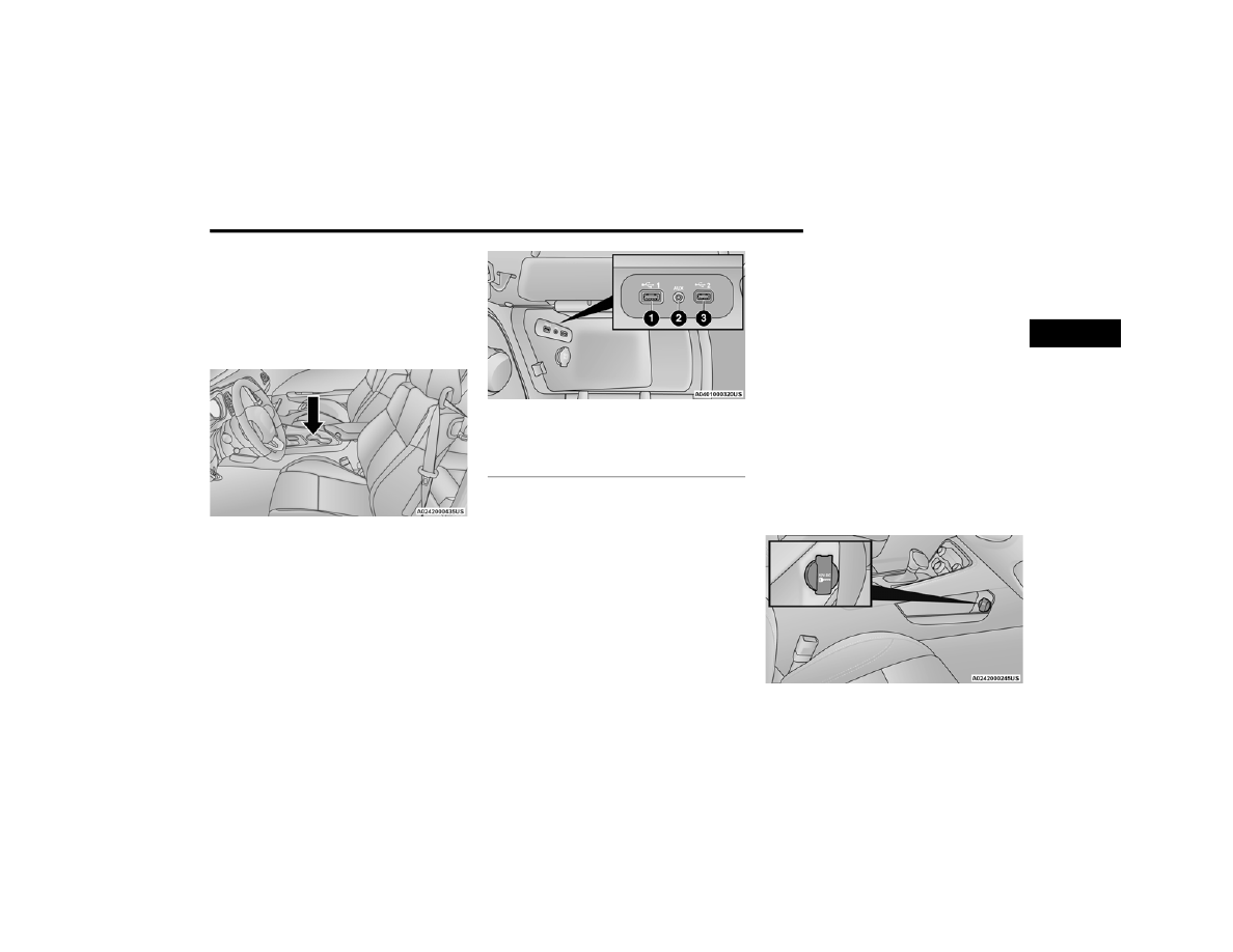
Located in the front storage area of the center 

console, this feature allows an external USB device 

to be connected to the audio system.
Plugging in a smartphone device to a USB port may 

activate Android Auto™ or Apple CarPlay® 

features, if equipped

USB/AUX Ports

NOTE:

Charge unsupported devices with the Charge Only 

USB ports. If an unsupported device is plugged into 

a Media USB port, a message will display on the 

touchscreen that the device is not supported by 

the system.

E

LECTRICAL

 P

OWER

 O

UTLETS


Your vehicle is equipped with 12 Volt (13 Amp) 

power outlets that can be used to power cellular 

phones, small electronics and other low powered 

electrical accessories. The power outlets are 

labeled with either a “key” or a “battery” symbol to 

indicate how the outlet is powered. Power outlets 

labeled with a key symbol can be powered when 

the ignition is in the ACC or ON/RUN position, while 

the outlets labeled with a battery symbol are 

connected directly to the battery and powered at 

all times.
These power outlets can also operate a 

conventional cigar lighter unit.
The front power outlet is located next to the 

storage area on the integrated center stack of the 

instrument panel.

Power Outlet — Integrated Center Stack Front

1 — USB 1 Port
2 — AUX Jack
3 — USB 2 Port

2

58

GETTING TO KNOW YOUR VEHICLE


(Continued)

NOTE:

The front integrated center stack power outlet can 

be changed from switched ignition to constant 

battery powered by moving the integrated center 

stack fuse #12 in the Rear Power Distribution 

Center from fuse location “IGN” to “B+”  

Ú

page 277.

In addition to the front center stack power outlet, 

there is also a power outlet located in the center 

console to the left of the media hub.

Power Outlet — Center Console

NOTE:

All accessories connected to these powered 

outlets should be removed or turned off when the 

vehicle is not in use to protect the battery against 

discharge.

Power Outlet Fuse Locations

1 — #12 Fuse 20A Yellow Power Outlet Integrated 

Center Stack
2 — #38 Fuse 20A Yellow Power Outlet Center 

Console

WARNING!

To avoid serious injury or death:

Only devices designed for use in this type of 

outlet should be inserted into any 12 Volt 

outlet.

Do not touch with wet hands.

Close the lid when not in use and while driving 

the vehicle.

If this outlet is mishandled, it may cause an 

electric shock and failure.

CAUTION!

Do not exceed the maximum power of 160 

Watts (13 Amps) at 12 Volts. If the 160 Watt 

(13 Amp) power rating is exceeded the fuse 

protecting the system will need to be replaced.

Power outlets are designed for accessory 

plugs only. Do not insert any other object in 

the power outlets as this will damage the 

outlet and blow the fuse. Improper use of the 

power outlet can cause damage not covered 

by your New Vehicle Limited Warranty.

GETTING TO KNOW YOUR VEHICLE

59

WINDOWS 

P

OWER

 W

INDOW

 C

ONTROLS

The window switches on the driver's door control 

all the door windows.

Power Window Switches

The passenger door window can also be operated 

by using the single window controls on the 

passenger door trim panel. The window controls 

will operate only when the ignition is in the ACC or 

ON/RUN position.

NOTE:

The power window switches will remain active for 

up to 10 minutes after the ignition is placed in the 

OFF position. Opening either front door will cancel 

this feature. The timing is programmable within 

Uconnect Settings  

Ú

page 123.

Many accessories that can be plugged in draw 

power from the vehicle's battery, even when 

not in use (i.e., cellular phones, etc.). Eventu

-

ally, if plugged in long enough, the vehicle's 

battery will discharge sufficiently to degrade 

battery life and/or prevent the engine from 

starting.

Accessories that draw higher power (i.e., 

coolers, vacuum cleaners, lights, etc.), will 

degrade the battery even more quickly. Only 

use these intermittently and with greater 

caution.

After the use of high power draw accessories, 

or long periods of the vehicle not being started 

(with accessories still plugged in), the vehicle 

must be driven a sufficient length of time to 

allow the alternator to recharge the vehicle's 

battery.

Power outlets are designed for accessory 

plugs only. Do not hang any type of accessory 

or accessory bracket from the plug. Improper 

use of the power outlet can cause damage.

CAUTION!

WARNING!

Never leave children unattended in a vehicle, 

and do not let children play with power windows. 

Do not leave the key fob in or near the vehicle, or 

in a location accessible to children, and do not 

leave the ignition of a vehicle equipped with 

Keyless Enter ‘n Go™ in the ACC or ON/RUN 

position. Occupants, particularly unattended 

children, can become entrapped by the windows 

while operating the power window switches. 

Such entrapment may result in serious injury or 

death.

2

60

GETTING TO KNOW YOUR VEHICLE


Automatic Window Features

The driver and, in some models, passenger power 

window switches have an Auto-Down feature. Push 

the window switch to the second detent, release, 

and the window will go down automatically.
To open the window part way, push the window 

switch to the first detent and release it when you 

want the window to stop.
To stop the window from going all the way down 

during the Auto-Down operation, pull up on the 

switch briefly.

W

IND

 B

UFFETING

Wind buffeting can be described as the perception 

of pressure on the ears or a helicopter-type sound 

in the ears. Your vehicle may exhibit wind buffeting 

with the windows down, or the sunroof (if 

equipped) in certain open or partially open 

positions. This is a normal occurrence and can be 

minimized. If the buffeting occurs with the windows 

open, partially close the windows to minimize the 

buffeting. If the buffeting occurs with the sunroof 

open, adjust the sunroof opening to minimize the 

buffeting or open any window.

POWER SUNROOF — IF EQUIPPED  

The power sunroof switch is located between the 

sun visors on the overhead console.

Power Sunroof Switch

1 — Sunroof Close Switch
2 — Sunroof Open Switch
3 — Vent Switch

WARNING!

Never leave children unattended in a vehicle, 

or with access to an unlocked vehicle. Never 

leave the key fob in or near the vehicle, or in a 

location accessible to children. Do not leave 

the ignition of a vehicle equipped with Keyless 

Enter ‘n Go™ in the ACC or ON/RUN position. 

Occupants, particularly unattended children, 

can become entrapped by the power sunroof 

while operating the power sunroof switch. 

Such entrapment may result in serious injury 

or death.

In a collision, there is a greater risk of being 

thrown from a vehicle with an open sunroof. 

You could also be seriously injured or killed. 

Always fasten your seat belt properly and 

make sure all passengers are also properly 

secured.

Do not allow small children to operate the 

sunroof. Never allow your fingers, other body 

parts, or any object, to project through the 

sunroof opening. Injury may result.

GETTING TO KNOW YOUR VEHICLE

61

O

PENING

 A

ND

 C

LOSING

 T

HE

 S

UNROOF

Express Open/Close
Push the switch rearward and release it within 

one-half second, the sunroof and sunshade will 

open automatically and stop at full open position.
Push the switch forward and release it within 

one-half second and the sunroof will close 

automatically from any position.
During Express Open or Express Close operation, 

any other movement of the sunroof switch will stop 

the sunroof.
Manual Open/Close
Push and hold the switch rearward, the sunroof 

and sunshade will open and automatically stop at 

full open position.
Push and hold the switch forward and the sunroof 

will close from any position and stop at a full closed 

position.
Any release of the switch during open or close 

operation will stop the sunroof movement. The 

sunroof will remain in a partially opened position 

until the switch is operated and held again.

Venting The Sunroof
Push and release the Vent switch within one half 

second and the sunroof will open to the vent 

position. During Express Vent operation, any other 

actuation of the sunroof switches will stop the 

sunroof operation.

P

INCH

 P

ROTECT

 F

EATURE

 — 

I

F

 E

QUIPPED

This feature will detect an obstruction in the 

closing of the sunroof during the Express Close 

operation. If an obstruction in the path of the 

sunroof is detected, the sunroof will automatically 

retract. Remove the obstruction if this occurs.

NOTE:

If three consecutive sunroof close attempts result 

in Pinch Protect reversals, Pinch Protect will 

disable and the sunroof must be closed in Manual 

Mode.

S

UNSHADE

 O

PERATION

The sunshade can be opened manually. However, 

the sunshade will open automatically as the 

sunroof opens.

NOTE:

The sunshade cannot be closed if the sunroof is 

open.

S

UNROOF

 M

AINTENANCE

Use only a non-abrasive cleaner and a soft cloth to 

clean the glass panel. Periodically check for and 

clear out any debris that may have collected in the 

tracks.

I

GNITION

 O

FF

 O

PERATION

NOTE:

The power sunroof switch can remain active in 

Accessory Delay for up to approximately 

10 minutes after the vehicle’s ignition is placed 

to the OFF position. Opening either front door 

will cancel this feature.

This feature is programmable using the Ucon

-

nect system  

Ú

page 123.

2

62

GETTING TO KNOW YOUR VEHICLE


HOOD    

O

PENING

 T

HE

 H

OOD


To open the hood, two latches must be released.
1. Pull the release lever located underneath the 

driver’s side of the instrument panel.

Hood Release Lever

2. Reach under the hood, push the safety catch 

to the left and lift the hood.

Hood Safety Catch Location

C

LOSING

 T

HE

 H

OOD

In one continuous motion, pull down on the front 

edge of the hood with moderate force until the 

angle is below the crossover point (where the gas 

props are no longer resisting) and let the hood 

continue to fall closed from its own inertia.

TRUNK    

O

PENING

 T

HE

 T

RUNK

The trunk may be opened in several ways:

Power trunk release button on the instrument 

panel

Trunk button on the key fob

Trunk Passive Entry button  

Ú

page 24

External release switch located on the under

-

side of the decklid overhang

NOTE:

The release feature will function only when the 

vehicle is unlocked.
With the ignition in the ON/RUN position, the trunk 

open symbol will display in the instrument cluster 

indicating that the trunk is open. The odometer 

display will reappear once the trunk is closed.
With the ignition in the OFF position, the trunk 

open symbol will display until the trunk is closed.
Power Trunk Release Button

The trunk can be opened from inside the 

vehicle using the power trunk release 

button located on the instrument panel 

to the left of the steering wheel.

WARNING!

Be sure the hood is fully latched before driving 

your vehicle. If the hood is not fully latched, it 

could open when the vehicle is in motion and 

block your vision. Failure to follow this warning 

could result in serious injury or death.

GETTING TO KNOW YOUR VEHICLE

63

NOTE:

The automatic transmission must be in PARK 

before the button will operate. For manual trans

-

missions, the vehicle must be in NEUTRAL.
Key Fob Trunk Release Button

Push the power trunk button on the key 

fob twice within five seconds to release 

the trunk.

Passive Entry Button
Push the trunk Passive Entry button which is 

located on the back of the trunk lid. With a valid 

Passive Entry key fob within 5 ft (1.5 m) of the 

trunk, push the Passive Entry button to open the 

trunk.

Trunk Passive Entry Button

C

LOSING

 T

HE

 T

RUNK

With one or more hands placed on the outside 

trunk surface push the trunk lid down until you 

hear the trunk lock latch into place.

NOTE:

Before closing the trunk lid, make sure your key fob 

is not inside the trunk area. The trunk will latch 

then automatically unlock if the key fob is 

detected, not allowing the key fob to be locked in 

the trunk area.

T

RUNK

 S

AFETY

Trunk Emergency Release
As a security measure, a trunk internal emergency 

release lever is built into the trunk latching 

mechanism. In the event of an individual being 

locked inside the trunk, the trunk can be opened 

by actuating the glow-in-the-dark handle attached 

to the trunk latching mechanism.

Trunk Emergency Release

WARNING!

Do not allow children to have access to the 

trunk, either by climbing into the trunk from 

outside, or through the inside of the vehicle. 

Always close the trunk lid when your vehicle is 

unattended. Once in the trunk, young children 

may not be able to escape, even if they entered 

through the rear seat. If trapped in the trunk, 

children can die from suffocation or heat stroke.

2

64  

GETTING TO KNOW YOUR INSTRUMENT PANEL

INSTRUMENT CLUSTER 

GETTING TO KNOW YOUR INSTRUMENT PANEL

65

I

NSTRUMENT

 C

LUSTER

 D

ESCRIPTIONS

1. Tachometer

Indicates the engine speed in revolutions 

per minute (RPM x 1000).

2. Instrument Cluster Display

When the appropriate conditions exist, this 

display shows the instrument cluster 

display messages  

Ú

page 65.

3. Speedometer

Indicates vehicle speed.

4. Temperature Gauge

The temperature gauge shows engine 

coolant temperature. Any reading within the 

normal range indicates that the engine 

cooling system is operating satisfactorily.

The gauge pointer will likely indicate a 

higher temperature when driving in hot 

weather, up mountain grades, or when 

towing a trailer. It should not be allowed to 

exceed the upper limits of the normal oper

-

ating range.

5. Fuel Gauge

The pointer shows the level of fuel in the 

fuel tank when the Keyless Push Button 

Ignition is in the ON/RUN position.

 The fuel pump symbol points to 

the side of the vehicle where the 

fuel door is located.

NOTE:

The hard telltales will illuminate for a bulb check 

when the ignition is first cycled.

INSTRUMENT CLUSTER DISPLAY

Your vehicle is equipped with an instrument cluster 

display, which offers useful information to the 

driver. With the ignition in the OFF mode, opening/

closing of a door will activate the display for 

viewing, and display the total miles, or kilometers, 

in the odometer. Your instrument cluster display is 

designed to display important information about 

your vehicle’s systems and features. Using a driver 

interactive display located on the instrument 

panel, your instrument cluster display can show 

you how systems are working and give you 

warnings when they are not. The steering wheel 

mounted controls allow you to scroll through the 

main menus and submenus. You can access the 

specific information you want and make selections 

and adjustments.

WARNING!

A hot engine cooling system is dangerous. You or 

others could be badly burned by steam or boiling 

coolant. It is recommended to call an authorized 

dealer for service if your vehicle overheats  

Ú

page 271.

CAUTION!

Driving with a hot engine cooling system could 

damage your vehicle. If the temperature gauge 

reads “H,” pull over and stop the vehicle. Idle the 

vehicle with the air conditioner turned off until 

the pointer drops back into the normal range. If 

the pointer remains on the “H,” turn the engine 

off immediately and call an authorized dealer for 

service.

3

66

GETTING TO KNOW YOUR INSTRUMENT PANEL


L

OCATION

 A

ND

 C

ONTROLS

The instrument cluster display features an 

interactive display which is located in the 

instrument cluster.

Instrument Cluster Display Location And Controls

This system conveniently allows the driver to select 

a variety of useful information by pushing the 

arrow buttons located on the left side of the 

steering wheel. The instrument cluster display 

menu items may consist of the following:

The system allows the driver to select information 

by pushing the following buttons mounted on the 

steering wheel:

Instrument Cluster Display Controls

1 — Instrument Cluster Display Screen
2 — Instrument Cluster Display Controls

Speedometer

Vehicle Info

Performance 

— If Equipped

Driver Assist — 

If Equipped

Fuel Economy Trip

Audio

Messages

Screen Setup

Diagnostics — 

If Equipped

Speed 

Warning —

If Equipped

1 — Left Arrow Button
2 — Up Arrow Button
3 — Right Arrow Button
4 — Down Arrow Button
5 — OK Button

GETTING TO KNOW YOUR INSTRUMENT PANEL

67

Up And Down Arrow Buttons:
Using the up   or down   arrow button allows 

you to cycle through the Main Menu Items.
Changes the Main Screen area and Menu Title 

area.
Left And Right Arrow Buttons:
Using the left   or right   arrow button allows 

you to cycle through the submenu items of the 

Main menu item.

NOTE:

Holding the up  or down  or left  or 
right  arrow button will loop the user through 

the currently selected menu or options 

presented on the screen.

Upon returning to a main menu, the last 

submenu screen viewed within that main menu 

will be displayed.

OK Button:
For Digital Speedometer:

Pushing the OK button changes units

(mph or km/h).

For Screen Setup:

OK button allows user to enter menu and 

submenus.

Within each submenu layer, the up   and 
down   arrow buttons will allow the user to 

select the item of interest.

Pushing the OK button makes the selection and 

a confirmation screen will appear (returning the 

user to the first page of the submenu).

Pushing the left   arrow button will exit each 

submenu layer and return to the main menu.

For the Trip and Fuel Economy menus (and 

Performance Timers) — If Equipped: 

Information is reset by pushing and holding the 

OK button.

E

NGINE

 O

IL

 L

IFE

 R

ESET


Oil Change Required
Your vehicle is equipped with an engine oil change 

indicator system. The “Oil Change Required” 

message will display in the instrument cluster 

display for five seconds after a single chime has 

sounded, to indicate the next scheduled oil change 

interval. The engine oil change indicator system is 

duty cycle based, which means the engine oil 

change interval may fluctuate, dependent upon 

your personal driving style.

Unless reset, this message will continue to display 

each time you place the ignition in the ON/RUN 

position. To turn off the message temporarily, push 

and release the OK or arrow buttons. To reset the 

oil change indicator system (after performing the 

scheduled maintenance), refer to the following 

procedure.
Vehicles Equipped With Keyless Enter ‘N Go™ — 

Ignition
Use the steering wheel instrument cluster display 

controls for the following procedure(s):
1. Without pressing the brake pedal, push the 

ENGINE START/STOP button and place the 

ignition in the ON/RUN position (do not start 

the engine).

2. Push and release the down   arrow button to 

scroll downward through the main menu to 

“Vehicle Info.”

3. Push and release the right   arrow button to 

access the ”Oil Life” screen.

3

68

GETTING TO KNOW YOUR INSTRUMENT PANEL


4. Push and hold the OK button to reset oil life. If 

conditions are met, the gauge and numeric 

display will update to show 100%. If conditions 

are not met a pop-up message of "To reset oil 

life engine must be off with ignition in run” will 

be displayed (for five seconds), and the user 

will remain at the Oil Life screen.

5. Push and release the up   or down   arrow 

button to return to previous main menu.

NOTE:

If the indicator message illuminates when you start 

the vehicle, the oil change indicator system did not 

reset. If necessary, repeat this procedure.
Secondary Method Of Resetting Engine Oil Life
1. Without pressing the brake pedal, push the 

ENGINE START/STOP button and place the 

ignition to the ON/RUN position (do not start 

the engine).

2. Fully press the accelerator pedal, slowly, three 

times within ten seconds.

3. Without pushing the brake pedal, push the 

ENGINE START/STOP button once to return the 

ignition to the OFF position.

NOTE:

If the indicator message illuminates when you start 

the vehicle, the oil change indicator system did not 

reset. If necessary, repeat this procedure.

P

ERFORMANCE

 S

HIFT

 I

NDICATOR


(PSI) — I

F

 E

QUIPPED

The PSI is enabled on vehicles with manual 

transmission, or when a vehicle with automatic 

transmission is in manual shift mode. The PSI 

provides the driver with a visual indication within 

the instrument cluster display when the driver 

configured gear shift point has been reached and 

the driver is still accelerating. This indication 

notifies the driver to change gear corresponding to 

the configured RPMs in the head unit.

I

NSTRUMENT

 C

LUSTER

 D

ISPLAY


S

ELECTABLE

 M

ENU

 I

TEMS

Push and release the up   or down   arrow 

button until the desired Selectable Menu item is 

displayed in the instrument cluster display.
Follow the Menu or submenu prompts as desired.

Speedometer

Push and release the up   or down   arrow 

button until the speedometer menu is displayed in 

the instrument cluster display. Push and release 

the OK button to toggle units (km/h or mph) of the 

speedometer.

Vehicle Info

Push and release the up   or down   arrow 

button until the “Vehicle Info” menu is displayed in 

the instrument cluster display. Push and release 
the right   or left   arrow button to scroll 

through the submenus items of “Vehicle Info.” 

Follow the directional prompts to access or reset 

any of the following “Vehicle Info” submenu items:
Tire Pressure Monitor
If tire pressure is OK for all tires, a vehicle ICON is 

displayed with tire pressure values in each corner 

of the ICON.
If one or more tires have low pressure, “Inflate Tire 

To XX” is displayed with the vehicle ICON and the 

tire pressure values in each corner of the ICON with 

the pressure value of the low tire are displayed in 

a different color than the other tire pressure value.
If the Tire Pressure system requires service, 

“Service Tire Pressure System” is displayed.
Tire PSI is an information only function and cannot 

be reset  

Ú

page 196.

GETTING TO KNOW YOUR INSTRUMENT PANEL

69

Coolant Temp

Displays the actual coolant temperature.

Trans Temp

Displays the actual transmission temperature.

Oil Temp

Displays the actual oil temperature.

Oil Pressure

Displays the actual oil pressure.

Oil Life
To reset the Oil Life, you must hold the OK button. 

The “Hold OK to Reset” instruction will be 

displayed at all times, but the following conditions 

will need to be met in order to reset Oil Life:

The vehicle must be off

The ignition must be in the ON/RUN position

If the conditions are met, holding the OK button will 

reset the gauge and the numeric display will return 

to 100%.
If the conditions are not met, a pop-up message 

will display for 5 seconds, describing the required 

conditions, and then the Oil Life screen will 

reappear.

Battery Voltage

Displays the actual battery voltage.

All Wheel Drive (AWD) Status — If Equipped

Displays the status of the All - Wheel Drive 

system.

Performance Features 

Push and release the up   or down   arrow 

button until the Performance menu is displayed in 
the instrument cluster display. Push the right   
or left   arrow button to enter the submenus.

The Performance Features include the following:

0-60 mph (0-100 km/h) Timer

Best

Last

Recent

Reaction Timer

0-100 mph (0-160 km/h) Timer

Best

Last

Recent

Reaction Timer

1/8 Mile (200 meters) Timer

Best

Last

Recent

Reaction Timer

1/4 Mile (400 meters) Timer

Best

Last

Recent

Reaction Timer

WARNING!

Measurement of vehicle statistics with the 

Performance Features is intended for 

off-highway or track use only and should not be 

done on any public roadways. It is recommended 

that these features be used in a controlled 

environment and within the limits of the law. The 

capabilities of the vehicle as measured by the 

performance pages must never be exploited in a 

reckless or dangerous manner, which can 

jeopardize the user’s safety or the safety of 

others. Only a safe, attentive, and skillful driver 

can prevent accidents.

3

70

GETTING TO KNOW YOUR INSTRUMENT PANEL


Braking Distance

Distance

From Speed

Current G-Forces

Peak G-Forces

Lap Timer

Lap History

Will list the last five laps with the best lap 

highlighted in green.

Top Speed

The following describes each feature and its 

operation:

Driver Assist — If Equipped

Adaptive Cruise Control (ACC) Menu
The instrument cluster display displays the current 

ACC system settings. The information displayed 

depends on ACC system status.
Push the ACC ON/OFF button (located on the 

steering wheel) until one of the following displays 

in the instrument cluster display:
Adaptive Cruise Control Off
When ACC is deactivated, the display will read 

“Adaptive Cruise Control Off.”

Adaptive Cruise Control Ready
When ACC is activated but the vehicle speed 

setting has not been selected, the display will read 

“Adaptive Cruise Control Ready.”
Push the SET + or the SET- button (located on the 

steering wheel) and the following will display in the 

instrument cluster display:
ACC SET
When ACC is set, the set speed will display in the 

instrument cluster.
If the Driver Assist main menu is not selected, an 

ACC pop-up message may display if any ACC 

activity occurs, which may include any of the 

following:

Distance Setting Change

System Cancel

Driver Override

System Off

ACC Proximity Warning

ACC Unavailable Warning

The instrument cluster display will return to the last 

display selected after five seconds of no ACC 

display activity  

Ú

page 99.

Fuel Economy

Two submenu pages; one with Current Value 

(instantaneous calculation of the fuel economy) 

displayed and one without the Current Value 
displayed (toggle the left   or right   arrow 

button to select one):

Current Fuel Economy (MPG, L/100 km, or 

km/L).

Range To Empty (miles or km).

Average Fuel Economy (MPG, L/100 km, or 

km/L).

The Max and Min values will correspond to the 

particular engine requirements.

Lower end of gauge will be displayed in an 

amber color and turn green as Fuel Economy 

improves.

Hold the OK button to reset average fuel 

economy information.

GETTING TO KNOW YOUR INSTRUMENT PANEL

71

Trip Info

Push and release the up   or down   arrow 

button until the Trip Menu item is displayed in the 
instrument cluster display. Toggle the left   
or right   arrow button to select Trip A or Trip B. 

The Trip information will display the following:

Distance – Shows the total distance (mi or km) 

traveled for Trip A or Trip B since the last reset.

Average Fuel Economy – Shows the average 

fuel economy (MPG, L/100km or km/L) of Trip A 

or Trip B since the last reset.

Elapsed Time – Shows the total elapsed time of 

travel since the last reset.

Hold the OK button to reset feature information.

Audio

This menu displays the Audio information of the 

currently playing audio source (e.g. FM radio).

Messages

This feature shows the number of stored warning 
messages, if any. Pushing the right   or left   

arrow button will allow you to scroll through the 

stored messages.

Screen Setup

Push and release the up   or down   arrow 

button until the Screen Setup Menu displays in the 

instrument cluster display. Push and release the 

OK button to enter the submenus. The Screen 

Setup feature allows you to change what 

information is displayed in the instrument cluster 

as well as the location that information is 

displayed.

1. Current Gear

On

Off

2. Odometer

Show

Hide

3. Gear Display

Full

Single

4. Restore Defaults

Ok

Cancel

Upper Left

Compass

Outside Temp Time

Range to 

Empty

Average (MPG, 

L/100 km, or 

km/L)

Current (MPG, 

L/100 km, or 

km/L)

Trip A Distance Trip B Distance None

Upper Right

Compass

Outside Temp Time

Range to 

Empty

Average (MPG, 

L/100 km, or 

km/L)

Current (MPG, 

L/100 km, or 

km/L)

Trip A Distance Trip B Distance None

Center

Menu Title

Compass

Outside Temp

Time

Range to 

Empty

Average (MPG, 

L/100 km, or 

km/L)

Current (MPG, 

L/100 km, or 

km/L)

Trip A Distance Trip B Distance

Audio 

Information

Digital Speed

None

Center

3

72

GETTING TO KNOW YOUR INSTRUMENT PANEL


B

ATTERY

 S

AVER

 O

N

/B

ATTERY

 S

AVER


M

ODE

 M

ESSAGE

 — E

LECTRICAL

 L

OAD


R

EDUCTION

 A

CTIONS

 — I

F

 E

QUIPPED


This vehicle is equipped with an Intelligent Battery 

Sensor (IBS) to perform additional monitoring of 

the electrical system and status of the vehicle 

battery.
In cases when the IBS detects charging system 

failure, or the vehicle battery conditions are 

deteriorating, electrical load reduction actions will 

take place to extend the driving time and distance 

of the vehicle. This is done by reducing power to or 

turning off non-essential electrical loads.
Load reduction is only active when the engine is 

running. It will display a message if there is a risk 

of battery depletion to the point where the vehicle 

may stall due to lack of electrical supply, or will not 

restart after the current drive cycle.
When load reduction is activated, the message 

“Battery Saver On” or “Battery Saver Mode” will 

appear in the instrument cluster.
These messages indicate the vehicle battery has a 

low state of charge and continues to lose electrical 

charge at a rate that the charging system cannot 

sustain.

NOTE:

The charging system is independent from load 

reduction. The charging system performs a diag

-

nostic on the charging system continuously.

If the Battery Charge Warning Light is on it may 

indicate a problem with the charging system  

Ú

page 74.

The electrical loads that may be switched off (if 

equipped), and vehicle functions which can be 

affected by load reduction:

Heated Seat/Vented Seats/Heated Wheel

Heated/Cooled Cup Holders — If Equipped

Rear Defroster And Heated Mirrors

HVAC System

115 Volts AC Power Inverter System

Audio and Telematics System

Loss of the battery charge may indicate one or 

more of the following conditions:

The charging system cannot deliver enough 

electrical power to the vehicle system because 

the electrical loads are larger than the capability 

of the charging system. The charging system is 

still functioning properly.

Turning on all possible vehicle electrical loads 

(e.g. HVAC to max settings, exterior and interior 

lights, overloaded power outlets +12 Volts, 

115 Volts AC, USB ports) during certain driving 

conditions (city driving, towing, frequent stop

-

ping).

Installing options like additional lights, upfitter 

electrical accessories, audio systems, alarms 

and similar devices.

Unusual driving cycles (short trips separated by 

long parking periods).

The vehicle was parked for an extended period 

of time (weeks, months).

The battery was recently replaced and was not 

charged completely.

The battery was discharged by an electrical load 

left on when the vehicle was parked.

The battery was used for an extended period 

with the engine not running to supply radio, 

lights, chargers, +12 Volts portable appliances 

like vacuum cleaners, game consoles and 

similar devices.


Content      ..     2      3      4      5     ..