Dodge Viper SRT-10 (ZB). Manual - part 77
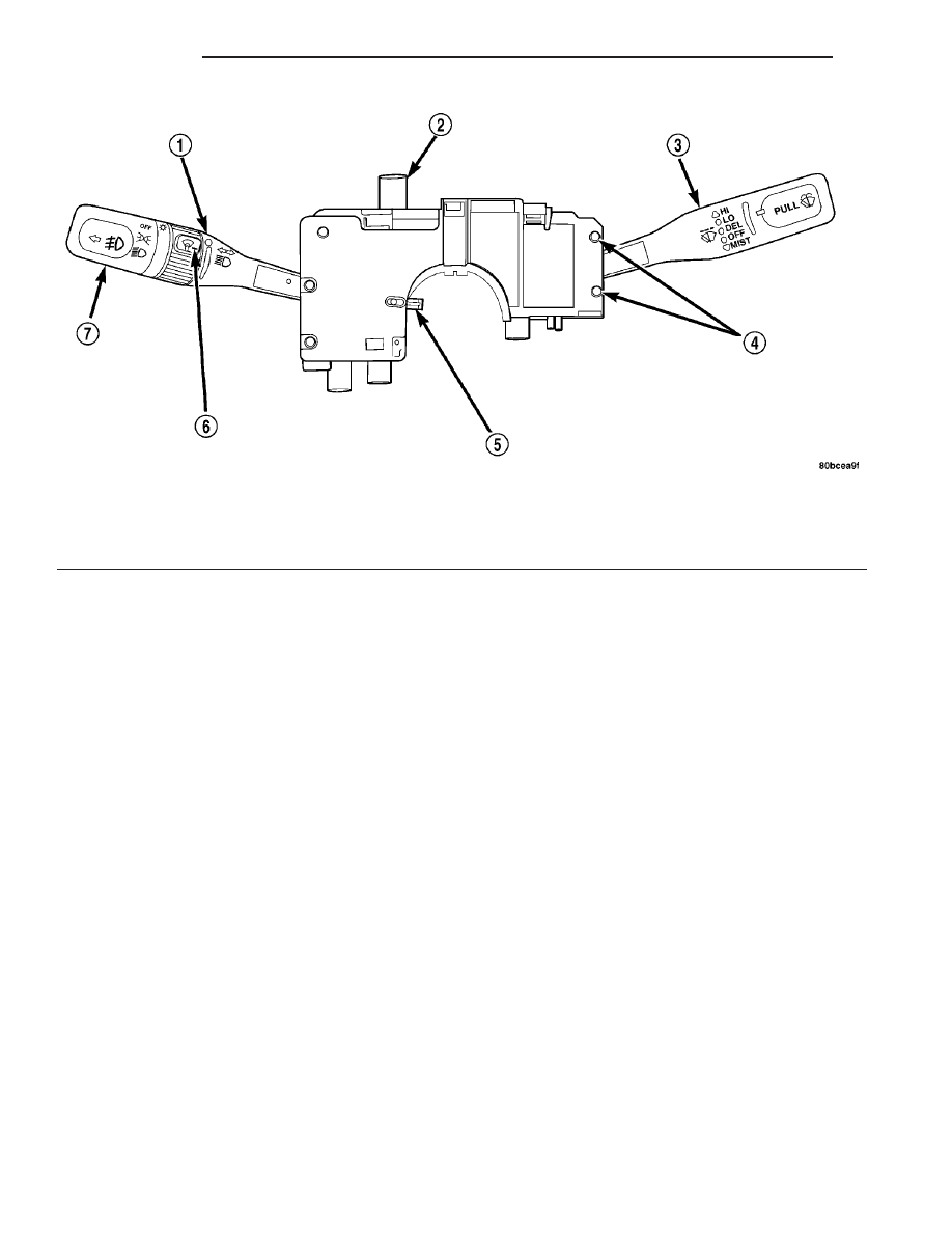
switch (Fig. 15), on the top of the steering column
between the steering wheel and the instrument
panel. The hazard switch is identifiable by a double
triangle on front of the button.
The hazard warning system allows the vehicle
operator to provide the drivers of other vehicles in
near proximity and optical indication that the vehicle
is disabled or is an obstacle to traffic flow. Unlike the
turn signal system, the hazard warning system has
battery current at all times, regardless of ignition
switch position.
OPERATION
LIGHTING
The multi-function switch provides input for the
exterior and interior lighting to the Body Control
Module (BCM). The switch is grounded through the
Body Control Module (BCM). When the ignition
switch is in the ACCESSORY or ON positions, bat-
tery current from a fuse in the Power Distribution
Center (PDC) is provided through a BCM controlled
ignition switch output (RUN/ACC) circuit. The BCM
controls the circuit protection and logic for the Low
Beam relay, High Beam, Park Lamps and Fog Lamp
circuitry. The BCM also controls the circuit protec-
tion and logic for the two RUN only feeds, RUN/AC-
CESSORY feed, and the Ignition Off Draw (IOD)
feed.
The multi-function switch controls the follow-
ing headlamp features and provides:
• Headlamp Beam Selection - The turn signal
control stalk on the left side of the multi-function
switch is pulled towards the steering wheel past a
detent, then released to actuate the headlamp beam
selection switch. Each time the control stalk is actu-
ated in this manner, the opposite headlamp mode
from what is currently selected will be activated. The
internal circuitry of the headlamp beam selection
switch directs the output of the headlamp switch to
the BCM and the BCM will activate the selected
headlamp beam.
• Headlamp Optical Horn - The turn signal con-
trol stalk is pulled towards the steering wheel to just
before a detent, to momentarily activate the head-
lamp high beams. The high beams will remain illu-
minated until the control stalk is released. The input
is detected by the BCM and the BCM will control the
output.
• Turn Signal Control - The turn signal control
stalk actuates the turn signal switch. When the control
stalk is moved in the upward direction, the right turn
signal circuitry is activated; and, when the control stalk
is moved in the downward direction, the left turn signal
circuitry is activated. The multi-function switch turn
signal circuitry simultaneously provides a signal to the
turn signal sense of the combination flasher to activate
or deactivate the flasher output, and directs the output
of the flasher to the proper turn signal lamps. The turn
Fig. 15 MULTI-FUNCTION SWITCH
1 - TURN SIGNAL CONTROL STALK
5 - CANCELLING CAM
2 - HAZARD WARNING SWITCH
6 - PANEL DIMMER/INTERIOR LIGHT SWITCH
3 - WINDSHIELD WIPER/WASHER CONTROL
7 - EXTERIOR LIGHTING CONTROL/FOG LAMP
4 - WINDSHIELD WIPER/WASHER SWITCH RETAINING SCREWS
8L - 16
LAMPS
ZB
MULTI-FUNCTION SWITCH (Continued)