Dodge Viper SRT-10 (ZB). Manual - part 76


  Index      Dodge     Dodge Viper SRT-10 (ZB) - service repair manual 2005 year


Search            


Content   ..  74  75  76  77   ..


Dodge Viper SRT-10 (ZB). Manual - part 76


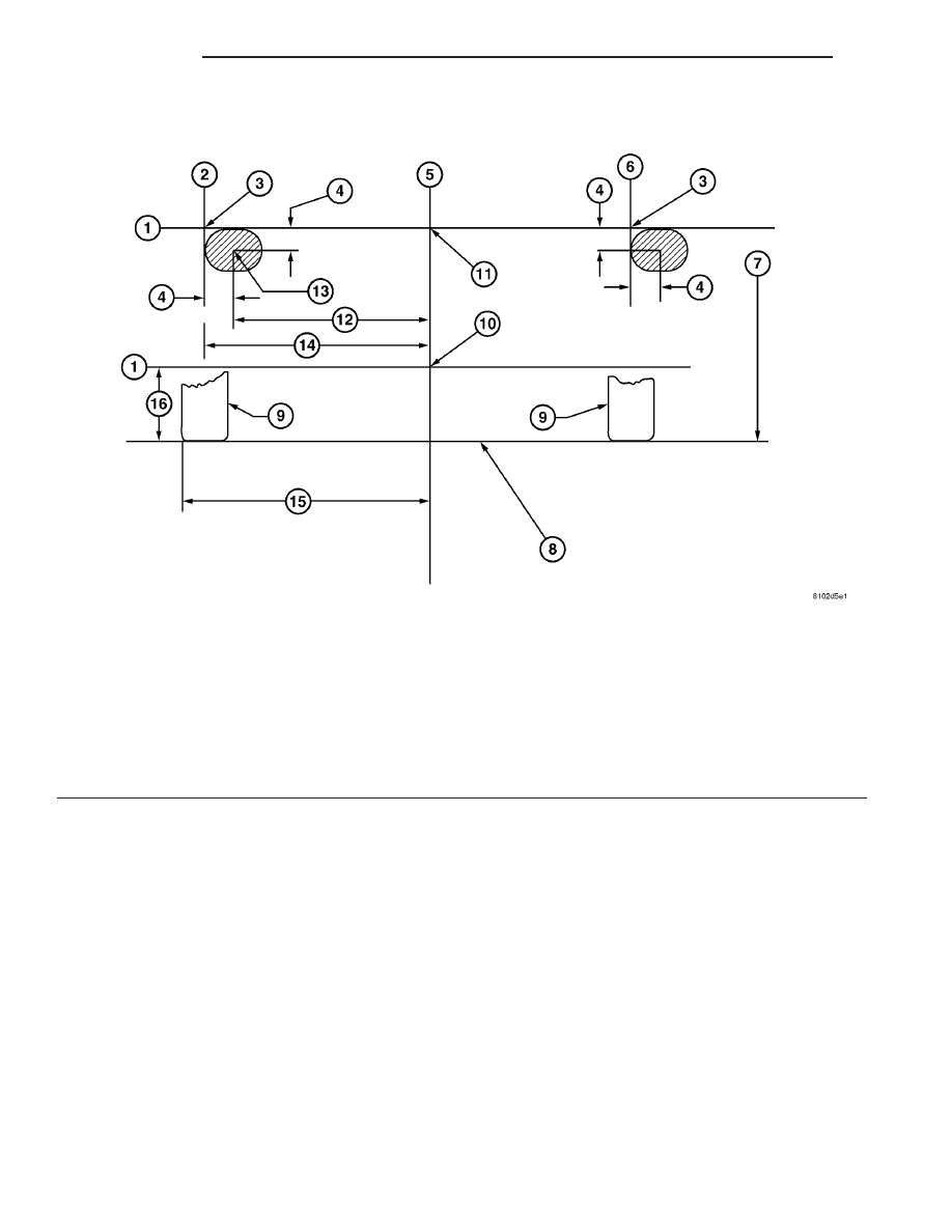
Fig. 12 HEADLAMP/FOG LAMP UNIT AIMING

1 - HORIZONTAL CENTERLINE OF HEADLAMP ON VEHICLE

9 - RIGHT TIRE

2 - VERTICAL CENTERLINE OF LEFT HEADLAMP

10 - FOG LAMP HORIZONTAL ALIGNMENT LINE

3 - CENTER OF VEHICLE HEADLAMP UNIT

11 - CENTER OF HORIZONTAL HEADLAMP LINE AND VEHICLE
CENTERLINE

4 - 4 INCHES

12 - 21.50 INCHES

5 - VERTICAL CENTERLINE OF VEHICLE

13 - CENTER OF LOW BEAM HIGH INTENSITY

6 - VERTICAL CENTERLINE OF RIGHT HEADLAMP

14 - 25.25 INCHES

7 - HEIGHT TO FLOOR OF HEADLAMP FILAMENT - 25.12
INCHES ± 2 INCHES

15 - 35.50 INCHES TO OUTSIDE OF FRONT TIRE

8 - FLOOR LEVEL

16 - 11.125 INCHES

8L - 12

LAMPS

ZB

HEADLAMP UNIT (Continued)

Fig. 13 HEADLAMP AIMING - EXPORT

1 - HORIZONTAL CENTERLINE OF HEADLAMP ON VEHICLE

8 - FLOOR LEVEL

2 - VERTICAL CENTERLINE OF LEFT HEADLAMP

9 - TIRES

3 - CENTER OF VEHICLE HEADLAMP UNIT

10 - FOG LAMP HORIZONTAL ALIGNMENT LINE

4 - 100 MM (4 IN.)

11 - IMAGE BREAK POINT

5 - VERTICAL CENTERLINE OF VEHICLE

12 - 628 MM (27.72 IN.)

6 - VERTICAL CENTERLINE OF RIGHT HEADLAMP

13 - 902 MM (35.50 IN.) TO OUTSIDE OF FRONT TIRE

7 - HEIGHT TO FLOOR OF HEADLAMP FILAMENT - 614 MM
(24.17 IN.)

14 - 282 MM (11.13 IN.)

ZB

LAMPS

8L - 13

HEADLAMP UNIT (Continued)

REMOVAL

(1) Open deck lid.
(2) Remove four bolts to battery compartment

cover and remove cover.

(3) Disconnect and isolate the battery negative

cable.

(4) Open hood.
(5) Remove front fender extension splash shield on

the respective side by removing the fasteners (Fig.
14).

(6) From just inside the engine compartment, just

to the right of the air cleaner housing, find and dis-
connect the headlamp unit wiring harness connector.
When disconnected, feed wire through inner fender
into wheel well.

(7) Remove the four bolts to the fender along the

inner edge of the engine compartment to allow the
fender to be lifted slightly upon headlamp unit
removal.

(8) From inside the wheel well, remove the two

nuts and bracket that attach the corner of the fascia
to the fender.

(9) From the underside, remove the one screw that

attaches the fender to the fascia support panel.

(10) Remove the three retaining nuts from the

underside of the headlamp unit.

(11) Lift up on the front of the fender slightly, then

lift the headlamp unit up and to the rear, into the
wheel well.

NOTE: Be careful not to lose the shims (if they are
present) they will be needed upon installation for
the proper headlamp unit alignment.

INSTALLATION

(1) If replacing headlamp unit, transfer the bulbs

to the new headlamp unit.

(2) Maneuver headlamp unit in the wheel well

opening and forward into the headlamp unit mount-
ing slots.

NOTE: If shims were present at removal, then rein-
sert the shims in the same place before tightening
headlamp unit nuts.

(3) Install the three retaining nuts on the under-

side of the headlamp unit. Torque nuts to 10 N·m (85
in. lbs.).

Install the one screw that attaches the fender to

the fascia support panel.

(4) Install the bracket and two nuts for the fender/

fascia attachment.

(5) Install the front fender extension splash shield

on the respective side by and the fasteners (Fig. 14).

(6) Connect the battery negative cable.
(7) Place battery access cover into place and install

four bolts.

(8) Close deck lid.
(9) Verify vehicle and system operation.
(10) Verify headlamp unit aim. If adjustment is

necessary,

(Refer

to

8

-

ELECTRICAL/LAMPS/

LIGHTING

-

EXTERIOR/HEADLAMP

UNIT

-

STANDARD PROCEDURE).

LICENSE PLATE LAMP

REMOVAL

(1) Open deck lid.
(2) Remove four bolts to battery compartment

cover and remove cover.

(3) Disconnect and isolate the battery negative

cable.

(4) Reach in behind the license plate lamp unit

and turn the respective bulb counterclockwise, pull
forward and remove.

(5) Pull the license plate lamp straight out and

remove from vehicle.

INSTALLATION

(1) Push the license plate lamp straight into the

lamp socket.

Fig. 14 FRONT FENDER EXTENSION SPLASH

SHIELD

1 - FENDER SPLASH SHIELD
2 - PUSH IN PIN FASTENER
3 - FENDER EXTENSION SPLASH SHIELD
4 - FRAME ASSEMBLY

8L - 14

LAMPS

ZB

HEADLAMP UNIT (Continued)

(2) Place the lamp socket into the license plate

lamp unit and turn the respective bulb clockwise
until stops.

(3) Connect the battery negative cable.
(4) Place battery access cover into place and install

four bolts.

(5) Close deck lid.
(6) Verify vehicle and system operation.

LICENSE PLATE LAMP UNIT

REMOVAL

(1) Open deck lid.
(2) From outside of trunk, remove the two license

plate lamp unit screws.

(3) Remove the two lamp sockets from the lamp

unit by turning 1/4 turn counterclockwise and pulling
outwards.

(4) Push lamp unit inward to deck lid.
(5) Remove lamp unit from vehicle.

INSTALLATION

(1) Install lamp unit into deck lid from inside.
(2) Push lamp unit through deck lid, line up

mounting holes.

(3) From outside of trunk, install the two license

plate lamp unit screws.

(4) Install the two lamp sockets into the lamp unit

by pushing into lamp unit and turning 1/4 turn
clockwise.

(5) Close deck lid.
(6) Verify vehicle and system operation.

MULTI-FUNCTION SWITCH

DESCRIPTION

The multi-function switch is secured to the upper

steering column housing at the top of the steering
column, just behind the steering wheel (Fig. 15). The
visible parts of the multi-function switch are the turn
signal control stalk w/exterior lighting controls that
extends through a dedicated opening in the left side
of the upper steering column shrouds, the windshield
wiper/washer stalk that extends through a dedicated
opening in the right side of the upper steering col-
umn shrouds, and the hazard warning switch push
button that protrudes through an opening in the
upper steering column shroud on the top of the steer-
ing column. The remainder of the switch, its mount-
ing provisions, and its electrical connections are all
concealed beneath the steering column shrouds. The
multi-function switch control stalk has both nomen-
clature and International Control and Display Sym-
bol graphics applied to it, which identify its many

functions. An International Control and Display Sym-
bol icon for “Hazard Warning” is applied to the top of
the hazard warning switch push button.

The switch housing and its controls are constructed

of molded black plastic. A connector receptacle with
up to twenty terminals is located on the back of the
switch housing and connects the switch to the vehicle
electrical system through a take out and connector of
the instrument panel wire harness.

The multi-function switch supports the following

functions and features:

• Continuous Wipe Modes - The control knob of

the multi-function switch provides two continuous
wipe switch positions, low speed or high speed.

• Intermittent Wipe Mode - The control knob of

the multi-function switch provides an intermittent
wipe mode with multiple delay interval positions.

• Washer Mode - The control stalk of the multi-

function switch provides washer system operation
when the button is pulled towards the driver.

• Wiper Mist Mode - Mist will cycle wipers when

stalk is pulled down.

• Hazard Warning Control - The internal cir-

cuitry and hardware of the multi-function switch pro-
vide detent switching for activation and deactivation
of the hazard warning system.

• Exterior Lighting Control - The internal cir-

cuitry and hardware of the multi-function switch pro-
vides an input to the BCM and the BCM controls for
activation and deactivation of exterior lighting.

• Headlamp Beam Selection - The internal cir-

cuitry and hardware of the multi-function switch pro-
vides an input to the BCM and the BCM controls
detent switching for selection of the headlamp high
or low beams.

• Headlamp Optical Horn - The internal cir-

cuitry and hardware of the multi-function switch
includes momentary switching of the headlamp high
beam circuits to provides an input to the BCM and
the BCM controls the optical horn feature (some-
times referred to as flash-to-pass), which allows the
vehicle operator to momentarily flash the headlamp
high beams as an optical signaling device.

• Turn Signal Control - The internal circuitry

and hardware of the multi-function switch provide
both momentary non-detent switching and detent
switching with automatic cancellation for both the
left and right turn signals.

The multi-function switch cannot be adjusted or

repaired. If any function of the switch is faulty, or if
the switch is damaged, the entire switch unit must
be replaced.

HAZARD WARNING SYSTEM

The hazard warning system is identified and actu-

ated by a push button located in the multi-function

ZB

LAMPS

8L - 15

LICENSE PLATE LAMP (Continued)


Content   ..  74  75  76  77   ..