Dodge Ram Truck 1500-2500-3500. Manual - part 2058


  Index      Dodge     Dodge Ram Truck 1500-2500-3500 - service repair manual 2005 year


Search            


Content   ..  2056  2057  2058  2059   ..


Dodge Ram Truck 1500-2500-3500. Manual - part 2058


REMOVAL

1. Remove the HVAC housing and place it on a work-

bench (Refer to 24 - HEATING & AIR CONDITION-
ING/DISTRIBUTION/HOUSING-HVAC

-

REMOVAL).

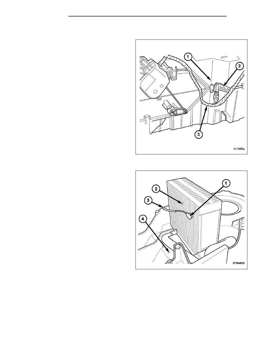
2. Remove the wire lead for the evaporator tempera-

ture sensor (2) from the retainer located on the
HVAC housing (1) and disconnect the sensor con-
nector from the HVAC wire harness (3).

3. Remove the lower half of the HVAC housing from

the upper half of the HVAC housing to gain access
to the A/C evaporator (Refer to 24 - HEATING &
AIR

CONDITIONING/DISTRIBUTION/HOUSING-

HVAC - DISASSEMBLY).

4. Carefully remove the probe of the evaporator tem-

perature sensor (1) from the fins of the A/C evap-
orator (2).

5. Remove the wire lead of the evaporator tempera-

ture sensor (3) from the upper half of the HVAC
housing (4).

24 - 232

CONTROLS

DR/DH

INSTALLATION

1. Install the probe of the evaporator temperature

sensor (1) between the fins of the A/C evaporator
(2).

2. Route the wire lead for the evaporator temperature

sensor (3) into the opening located on the upper
half of the HVAC housing (4).

3. Assemble the HVAC housing (Refer to 24 - HEAT-

ING

&

AIR

CONDITIONING/DISTRIBUTION/

HOUSING-HVAC - ASSEMBLY).

4. Install the wire lead of the evaporator temperature

sensor (2) to the retainer located on the HVAC
housing (1) and connect the sensor connector to
the HVAC wire harness (3).

5. Install the HVAC housing (Refer to 24 - HEATING

& AIR CONDITIONING/DISTRIBUTION/HOUSING-
HVAC - INSTALLATION).

DR/DH

CONTROLS

24 - 233

SWITCH-BLOWER MOTOR

DESCRIPTION

The blower motor is controlled by a rotary-type blower
motor switch (6), mounted in the A/C-heater control
(1). The switch allows the selection of one of four dif-
ferent blower motor speeds and includes an Off
position.

OPERATION

The blower motor switch provides a ground path through the A/C-heater control. The blower motor switch directs the
ground path through the appropriate blower motor resistor wires, as required to achieve the selected blower motor
speed.

The blower motor switch is diagnosed using a DRBIII

T

scan tool (Refer to 24 - HEATING & AIR CONDITIONING -

DIAGNOSIS AND TESTING and to 24 - HVAC Electrical Diagnostics for more information).

The blower motor switch cannot be repaired and, if faulty or damaged, the entire A/C-heater control must be
replaced (Refer to 24 - HEATING & AIR CONDITIONING/CONTROLS/CONTROL-A/C HEATER - REMOVAL).

TRANSDUCER-A/C PRESSURE

DESCRIPTION

The A/C pressure transducer (1) is a switch that is
installed on a fitting located on the A/C discharge line.
An internally threaded fitting on the A/C pressure
transducer connects it to the externally threaded
Schrader-type fitting on the A/C discharge line. A rub-
ber O-ring seals the connection between the A/C pres-
sure transducer and the discharge line fitting. The A/C
pressure transducer is connected to the vehicle elec-
trical system by a molded plastic connector with three
terminals.

24 - 234

CONTROLS

DR/DH

OPERATION

The A/C pressure transducer monitors the pressures in the high side of the refrigerant system through its connection
to a fitting on the A/C discharge line. The A/C pressure transducer will change its internal resistance in response to
the pressures it monitors. A Schrader-type valve in the A/C discharge line fitting permits the A/C pressure transducer
to be removed or installed without disturbing the refrigerant in the A/C system.

The A/C pressure transducer will change its internal resistance in response to the pressures it monitors. The pow-
ertrain control module (PCM) or the engine control module (ECM) (depending on engine application) provides a five
volt reference signal and a sensor ground to the A/C pressure transducer, then monitors the output voltage of the
transducer on a sensor return circuit to determine refrigerant pressure. The PCM/ECM is programmed to respond to
this and other sensor inputs by controlling the operation of the A/C compressor clutch and the radiator cooling fan
to help optimize A/C system performance and to protect the system components from damage. The PCM will dis-
engage the A/C compressor clutch when high side pressure rises above 3172 kPa (460 psi) and re-engage the
clutch when high side pressure drops below 1999 kPa (290 psi). The A/C pressure transducer will also disengage
the A/C compressor clutch if the high side pressure drops below 193 kPa (28 psi) and will re-engage the clutch
when the high side pressure rises above 234 kPa (34 psi). If the refrigerant pressure rises above 1655 kPa (240
psi), the PCM will actuate the cooling fan. The A/C pressure transducer signal to the PCM/ECM will also prevent the
A/C compressor clutch from engaging when ambient temperatures are below about 10° C (50° F) due to the pres-
sure/temperature relationship of the refrigerant.The A/C pressure transducer input to the PCM/ECM will also prevent
the A/C compressor clutch from engaging when ambient temperatures are below about 10° C (50° F) due to the
pressure/temperature relationship of the refrigerant.

The A/C pressure transducer is diagnosed using a DRBIII

T

scan tool. Refer to 9 - Engine Electrical Diagnostics for

more information.

The A/C pressure transducer cannot be adjusted or repaired and, if faulty or damaged, it must be replaced.

REMOVAL

NOTE: It is not necessary to discharge the refrig-
erant system to replace the A/C pressure trans-
ducer.

1. Disconnect and isolate the negative battery cable.

2. Disconnect the wire harness connector (1) from the

A/C pressure transducer (2) located on the A/C dis-
charge line (3).

3. Remove the A/C pressure transducer from the fit-

ting on the A/C discharge line and remove and dis-
card the O-ring seal.

DR/DH

CONTROLS

24 - 235


Content   ..  2056  2057  2058  2059   ..