Content .. 2055 2056 2057 2058 ..
Dodge Ram Truck 1500-2500-3500. Manual - part 2057
INSTALLATION
NOTE: Refer to the fuse and relay layout map on
the inside of the IPM cover for A/C clutch relay
location.
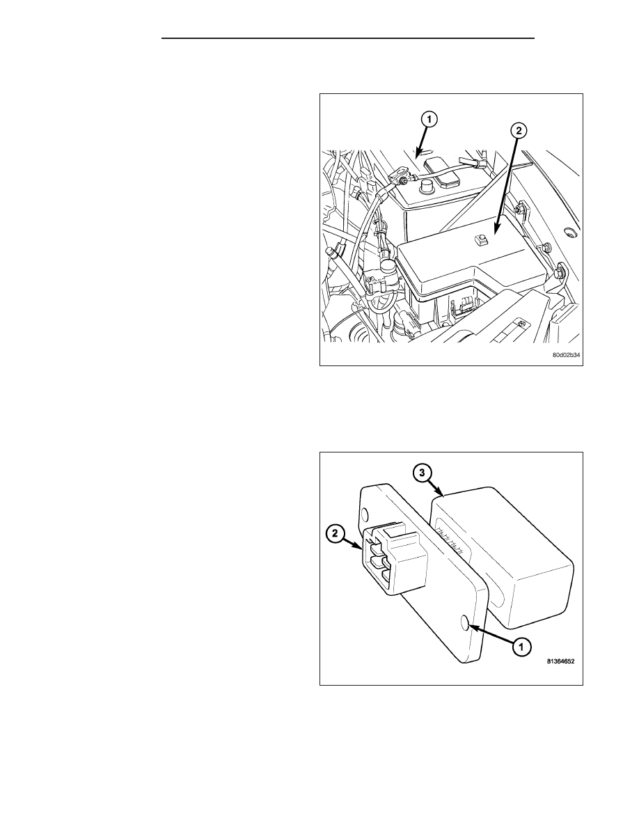
1. Position the A/C clutch relay into the receptacle of
the integrated power module (IPM) (2).
2. Align the A/C clutch relay terminals with the termi-
nal cavities in the IPM receptacle and push down
firmly on the relay until the terminals are fully
seated.
3. Install the cover onto the IPM.
4. Reconnect the negative battery cable (1).
RESISTOR-BLOWER MOTOR
DESCRIPTION
The blower motor resistor is mounted to the bottom of
the HVAC housing, directly behind the glove box. The
blower motor resistor consists of a molded plastic
mounting plate (1) with an integral wire connector
receptacle (2). Concealed behind the mounting plate
are coiled resistor wires contained within a ceramic
heat sink (3).
OPERATION
The blower motor resistor is connected to the vehicle electrical system through a dedicated wire lead and connector
of the HVAC wire harness. The blower motor resistor has multiple resistor wires, each of which will reduce the
current flow through the blower motor to change the blower motor speed.
The blower motor switch in the heating-A/C system directs the ground path for the blower motor through the correct
resistor wire to obtain the selected speed. With the blower motor control in the lowest speed position, the ground
path for the blower motor is applied through all of the resistor wires. Each higher speed selected with the blower
24 - 228
CONTROLS
DR/DH