Content .. 1445 1446 1447 1448 ..
Dodge Ram Truck 1500-2500-3500. Manual - part 1447
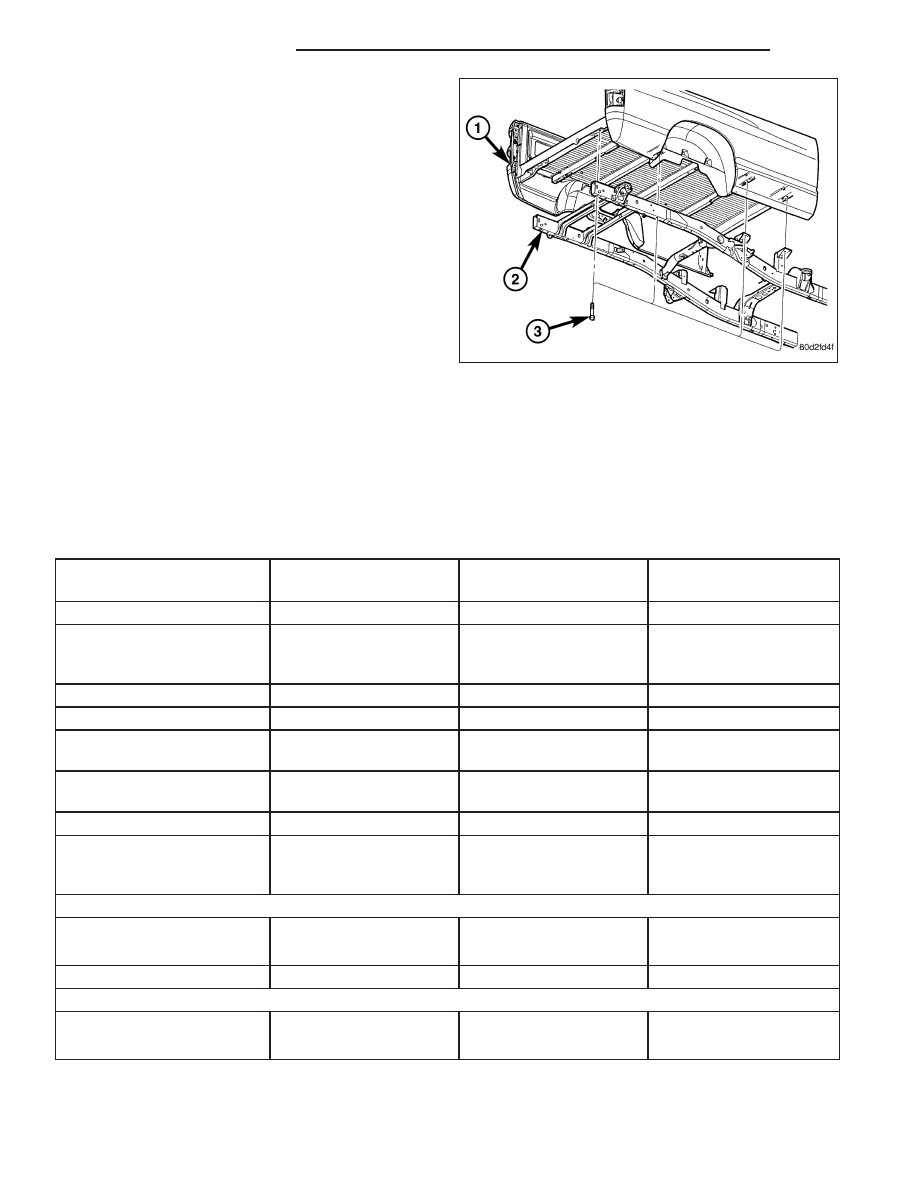
28. Install the cargo box (1) (Refer to 23 - BODY/EX-
TERIOR/CARGO BOX - INSTALLATION).
29. Reconnect the battery negative cable.
SPECIFICATIONS
WELD PROCESS
CAUTION: All welds should conform to DaimlerChrysler vehicle engineering process standard “ps 9472”.
WELDING PARAMETERS
WELDING PROCESS
FLUX CORED ARC
GAS METAL ARC
(MIG)*
SHIELDED METAL ARC
(STICK)
Material Thickness
3.7 mm to 4.2 mm
3.7 mm to 4.2 mm
3.7 mm to 4.2 mm
Electrode Type
Lincoln Electrical Co.
Product #: NR-211 MP
(Do Not Substitute)
AWS ER70S-3
(Do Not Substitute)
** AWS E 7018
Electrodes Size Inches
.045 Tubular
.035 Solid
3/32
9
Electrode Stick Out
3/8
9
- 1/2
9
1/2
9
- 5/8
9
N/A
Polarity
Electrode
9
-
9
Work Piece
9
+
9
Electrode
9
+
9
Work Piece
9
-
9
Electrode
9
+
9
Work Piece
9
-
9
Shielding Gas
Self Shielded
75% Ar
25% CO2
Self Shielded
Gas Flow Rate
N/A
25 - 35 CFM
N/A
Wire Feed Speed
(inches per minute)
110 - 130 Vertical Down
70 - 90 Flat & Overhead
245 - 250 Vertical Down
210 - 225 Flat &
Overhead
N/A
Approximate Amperage
Vertical
110 - 130
175
85 (3/32
9
Diameter)
Flat & Overhead
70 - 90
155
90 (3/32
9
Diameter)
Voltage
15 - 18
19 - 20
N/A
Direction of Welding
Vertical
Vertical Down Hill (only)
Vertical Down Hill (only)
Vertical - Up Hill (only)
Flat & Overhead
Flat - Push or Drag
Flat - Push or Drag
Flat - Drag
*First choice - Gas Metal Arc Welding Process: Butt joints - apply two layers (passes) of weld metal. First pass
should only fill approximately
1
⁄
2
the thickness. Vertical position welds - maintain electrode wire at leading edge of
weld puddle while traveling down hill to produce maximum penetration into the sleeve. These techniques work for
FCAW as well.
13 - 38
FRAME & BUMPERS
DR/DH