Content .. 1165 1166 1167 1168 ..
Dodge Ram Truck 1500-2500-3500. Manual - part 1167
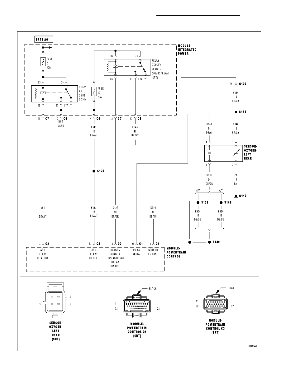
P0137-O2 SENSOR 1/2 CIRCUIT LOW
9 - 1590
ENGINE - ELECTRICAL DIAGNOSTICS - SRT-10
DR/DH
|
|
|
Content .. 1165 1166 1167 1168 ..
P0137-O2 SENSOR 1/2 CIRCUIT LOW 9 - 1590 ENGINE - ELECTRICAL DIAGNOSTICS - SRT-10 DR/DH |