Dodge Durango (DN). Manual - part 196
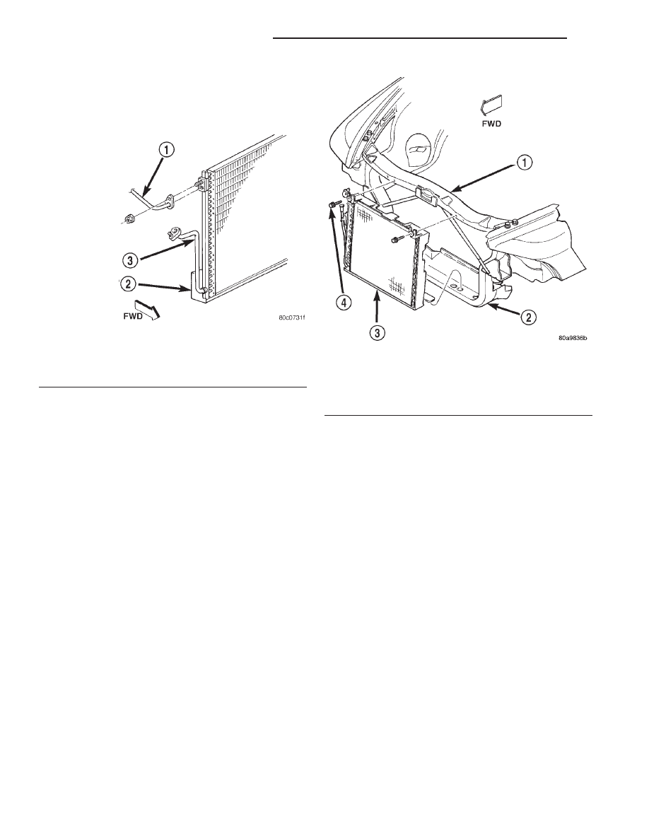
(3) Disconnect the refrigerant line fitting that
secures the discharge line to the condenser inlet (Fig.
37). Install plugs in, or tape over all of the opened
refrigerant line fittings.
(4) Disconnect the refrigerant line fitting that
secures the liquid line to the condenser outlet. Install
plugs in, or tape over all of the opened refrigerant
line fittings.
(5) Remove the two screws that secure the radiator
and fan shroud module to the inside of the upper
radiator crossmember.
(6) On models equipped with a V-8 engine, remove
the radiator from the engine compartment. Refer to
Cooling Systems for the procedures.
(7) Remove the two screws that secure the con-
denser to the outside of the upper radiator cross-
member (Fig. 38).
(8) Tilt the top of the radiator and fan shroud
module towards the engine, using care not to damage
the radiator fins on the engine cooling fan.
(9) With the radiator and fan shroud module
tilted, carefully lift the condenser upwards until the
lower condenser mounts are clear of the isolators in
the lower crossmember.
(10) Remove the condenser from the vehicle.
INSTALLATION
(1) With the radiator and fan shroud module tilted
towards the engine, carefully position the lower con-
denser mounts in the lower crossmember isolators.
(2) Reinstall the two screws that secure the con-
denser to the outside of the upper radiator cross-
member and tighten to 10.7 N·m (95 in. lbs.).
(3) On models equipped with a V-8 engine, rein-
stall the radiator to the engine compartment. Refer
to Cooling Systems for the procedures.
(4) Reinstall the two screws that secure the radia-
tor and fan shroud module to the inside of the upper
radiator crossmember.
(5) Remove the plugs or tape from the refrigerant
line fittings on the liquid line and the condenser out-
let. Connect the liquid line to the condenser outlet.
Tighten the fitting to 25.99
63.39 N·m (230 630 in.
lbs.).
(6) Remove the plugs or tape from the refrigerant
line fittings on the discharge line and the condenser
inlet. Connect the discharge line to the condenser
inlet. Tighten the fitting to 25.99
63.39 N·m (230
630 in. lbs.).
(7) Check that all of the condenser and radiator
air seals are in their proper locations.
(8) Connect the battery negative cable.
(9) Evacuate the refrigerant system. See Refriger-
ant System Evacuate in the Service Procedures sec-
tion of this group.
(10) Charge the refrigerant system. See Refriger-
ant System Charge in the Service Procedures section
of this group.
Fig. 37 Condenser Line Fittings
1 – DISCHARGE LINE
2 – CONDENSOR
3 – TO LIQUID LINE
Fig. 38 Condenser Remove/Install - Typical
1 – UPPER CROSSMEMBER
2 – LOWER CROSSMEMBER
3 – CONDENSER
4 – SCREW
24 - 42
HEATING AND AIR CONDITIONING
DN
REMOVAL AND INSTALLATION (Continued)