Dodge Durango (DN). Manual - part 195
INSTALLATION
NOTE: If
a
replacement
compressor
is
being
installed, be certain to check the refrigerant oil
level. See Refrigerant Oil Level in the Service Pro-
cedures section of this group. Use only refrigerant
oil of the type recommended for the compressor in
the vehicle.
(1) Install the compressor to the mounting bracket.
Tighten the four mounting screws to 27 N·m (20 ft.
lbs.).
(2) Remove the tape or plugs from all of the
opened refrigerant line fittings. Install the suction
and discharge line manifold to the compressor. See
Suction and Discharge Line in the Removal and
Installation section of this group for the procedures.
(3) Install the serpentine drive belt. Refer to
Group 7 - Cooling System for the procedures.
(4) Plug in the compressor clutch coil wire harness
connector.
(5) Connect the battery negative cable.
(6) Evacuate the refrigerant system. See Refriger-
ant System Evacuate in the Service Procedures sec-
tion of this group.
(7) Charge the refrigerant system. See Refrigerant
System Charge in the Service Procedures section of
this group.
COMPRESSOR CLUTCH
The refrigerant system can remain fully-charged
during compressor clutch, pulley, or coil replacement.
The compressor clutch can be serviced in the vehicle.
REMOVAL
(1) Disconnect and isolate the battery negative
cable.
(2) Remove the serpentine drive belt. Refer to
Group 7 - Cooling System for the procedures.
(3) Unplug the compressor clutch coil wire harness
connector.
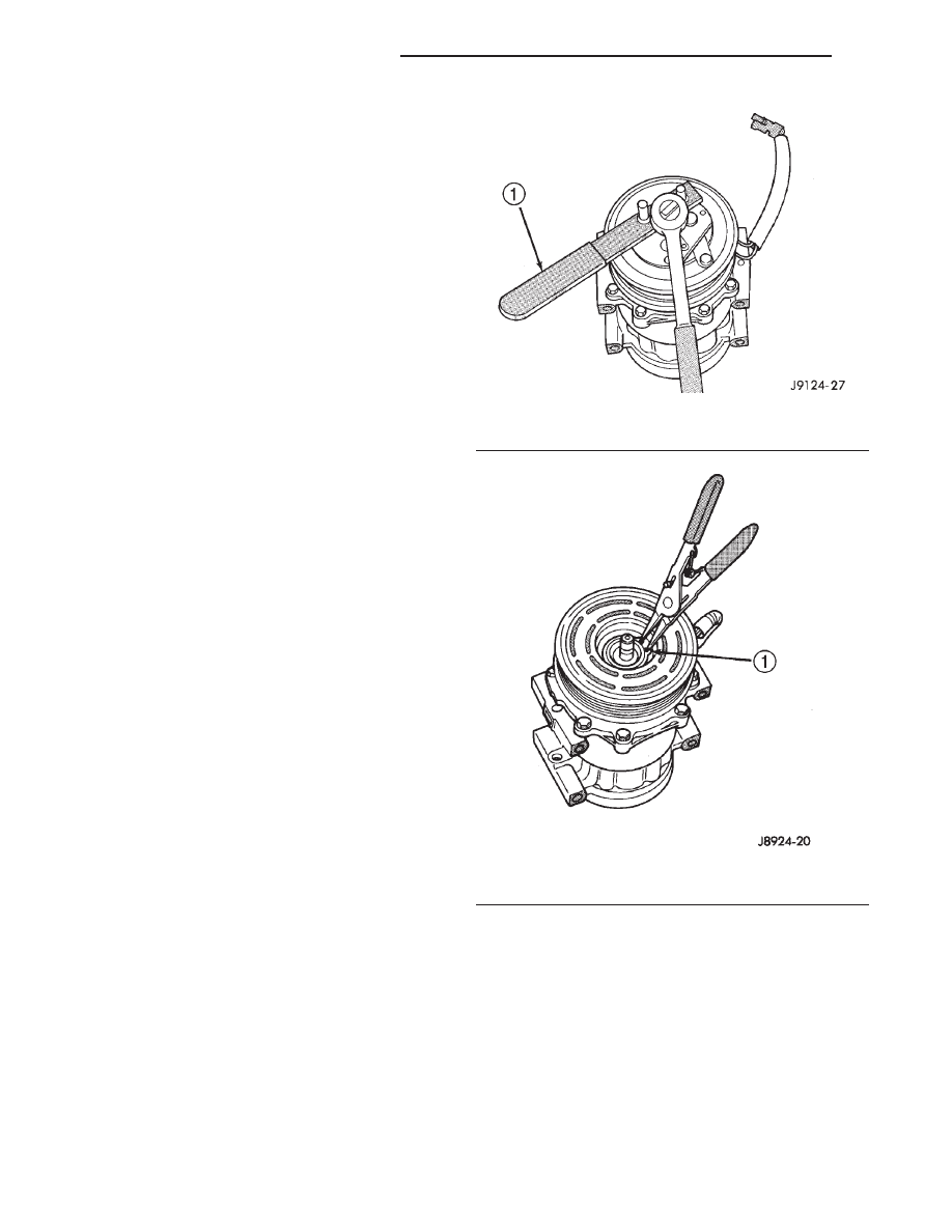
(4) Insert the two pins of the spanner wrench
(Special Tool 6462 in Kit 6460) into the holes of the
clutch plate. Hold the clutch plate stationary and
remove the hex nut (Fig. 26).
(5) Remove the clutch plate and the clutch shims.
(6) Remove the external front housing snap ring
with snap ring pliers (Fig. 27).
(7) Install the lip of the rotor puller (Special Tool
C-6141-1 in Kit 6460) into the snap ring groove
exposed in Step 6, and install the shaft protector
(Special Tool C-6141-2 in Kit 6460) (Fig. 28).
(8) Install the puller through-bolts (Special Tool
C-6461) through the puller flange and into the jaws
of the rotor puller and tighten (Fig. 29). Turn the
puller center bolt clockwise until the rotor pulley is
free.
(9) Remove the screw and retainer from the clutch
coil lead wire harness on the compressor front hous-
ing (Fig. 30).
(10) Remove the snap ring from the compressor
hub and remove the clutch field coil (Fig. 31). Slide
the clutch field coil off of the compressor hub.
Fig. 26 Clutch Nut Remove
1 – FRONT PLATE SPANNER
Fig. 27 External Snap Ring Remove
1 – EXTERNAL SNAP RING
24 - 38
HEATING AND AIR CONDITIONING
DN
REMOVAL AND INSTALLATION (Continued)