Chrysler Le Baron, Dodge Dynasty, Plymouth Acclaim. Manual - part 354
CONDITION: NO SEAT TRACK FRONT UP OR
DOWN MOVEMENT IN THE RECALL MODE,
SEAT TRACK FRONT WILL MOVE UP OR
DOWN BY MANUAL SWITCH ACTUATION
WITHOUT STALL DETECTION.
PROCEDURE
(1) Check for a voltage at pin 2 of the control mod-
ule 21-way connector. Less than 5 volts for the seat
track front full up and more than 0 volts when fully
down.
(2) Check for a voltage at pin 2 of the natural
5-way connector. Same as in step (1) above. With the
ground lead of the meter at pin 4 of this connector. If
the voltage reading is at 0 volts, disconnect the
5-way natural connector and check for a short to
ground in the harness. If no short is found, reconnect
the connector and continue the procedure.
(3) Check for the voltage to vary as noted above, if
it does not vary as the seat track front is moved up
and down, the sensing potentiometer is defective. Re-
place the seat motor package assembly. After re-
placement of the seat motor package, reconnect all
wiring connectors and reinstall seat assembly in ve-
hicle. Operate the switches manually to cause maxi-
mum seat movement in all directions. Perform the
memory seat diagnostic self check so the control
module will learn the new soft limits of the assem-
bly.
CONDITION: NO SEAT TRACK REAR UP OR
DOWN MOVEMENT IN THE RECALL MODE,
SEAT TRACK REAR WILL MOVE UP OR DOWN
BY MANUAL SWITCH ACTUATION WITHOUT
STALL DETECTION.
PROCEDURE
(1) Check for a voltage at pin 13 of the control
module 21-way connector. Less than 5 volts for the
seat track rear full up and more than 0 volts when
fully down.
(2) Check for a voltage at pin 3 of the natural
5-way connector. Same as in step (1) above. The
ground lead connected to pin 4 of the 5-way connec-
tor. If the voltage reading is at 0 volts, disconnect
the 5-way natural connector and check for a short to
ground in the harness. If no short is found, reconnect
the connector and continue the procedure.
(3) Check for the voltage to vary as noted above, if
it does not vary as the seat track rear is moved up
and down, the sensing potentiometer is defective. Re-
place the seat motor package assembly. After re-
placement of the seat motor package, reconnect all
wiring connectors and reinstall seat assembly in ve-
hicle. Operate the switches manually to cause maxi-
mum seat movement in all directions. Perform the
diagnostic self seat check so the control module will
learn the new soft limits of the assembly.
CONDITION: NO MOVEMENT OF THE SEAT,
SEAT WILL MOVE IN THE RECALL MODE
ONLY.
PROCEDURE
(1) Check for battery voltage to terminal 3 of driv-
er’s power seat switch.
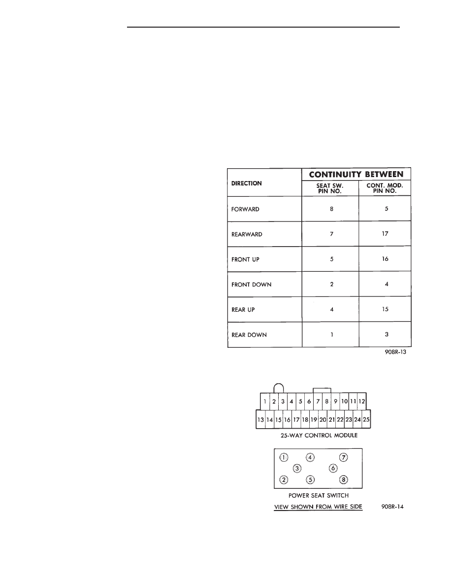
(2) Check for continuity of driver’s power seat
switch. Refer to Memory Seat Switch Continuity
(Fig. 19). If switch is good, check for continuity be-
tween the driver’s door switch and the 25-way con-
nector in the control module in the driver’s seat
(Figs. 21 and 22).
Fig. 21 Driver’s Door Switch to 25-Way Connector at
the Seat Control Module Continuity
Fig. 22 Control Module and Seat Switch Pin
Location
8R - 14
POWER SEATS
Ä