Chrysler Voyager (2022 year). Manual in english - page 5
 

  Index      Manuals     Chrysler Voyager (2022 year). Manual in english


Search            copyright infringement  


Content      ..     3      4      5      6     ..


Chrysler Voyager (2022 year). Manual in english - page 5


72

GETTING TO KNOW YOUR VEHICLE


Power Outlet Fuse Locations

WINDOWS

P

OWER

 W

INDOWS

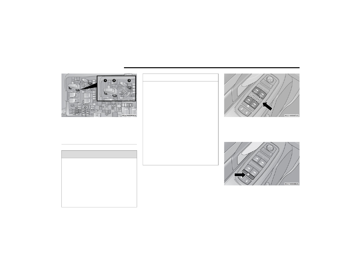
The window switches on the driver’s door trim 

panel control all of the door windows.

Driver’s Power Window Controls

The driver may lock out the rear power windows by 

pushing the bar control just below the power 

window controls.

Power Window Lockout Switch

The window switches will operate only when the 

ignition is in the ON/RUN or ACC position and 

during power accessory delay.

1 — F95A (Ignition)/F95B (Battery) Front Power 

Outlet 10A (If Equipped)
2 — F85 Cigar Lighter 20A
3 — F60 RR Cargo Power Outlet 20A

WARNING!

To avoid serious injury or death:

Only devices designed for use in this type of 

outlet should be inserted into any 12 Volt 

outlet.

Do not touch with wet hands.

Close the lid when not in use and while driving 

the vehicle.

If this outlet is mishandled, it may cause an 

electric shock and failure.

CAUTION!

Many accessories that can be plugged in draw 

power from the vehicle's battery, even when 

not in use (i.e., cellular phones, etc.). Eventu

-

ally, if plugged in long enough, the vehicle's 

battery will discharge sufficiently to degrade 

battery life and/or prevent the engine from 

starting.

Accessories that draw higher power (i.e., 

coolers, vacuum cleaners, lights, etc.) will 

degrade the battery even more quickly. Only 

use these intermittently and with greater 

caution.

After the use of high power draw accessories, 

or long periods of the vehicle not being started 

(with accessories still plugged in), the vehicle 

must be driven a sufficient length of time to 

allow the generator to recharge the vehicle's 

battery.

GETTING TO KNOW YOUR VEHICLE

73

NOTE:

Power Window controls will also remain active for 

up to 10 minutes after the ignition has been 

placed in the OFF position, depending upon the 

accessory delay setting. Opening a front door will 

cancel this feature.
There is a single control on the front passenger’s 

door trim panel which operates the passenger door 

window and a set of controls that lock and unlock 

all doors. The controls will operate only when the 

ignition is in the ON/RUN or ACC position and 

during power accessory delay.
Sliding Side Door Power Window Control — 

If Equipped
Second row passengers may open and close the 

sliding door window by a single control on the door 

handle assembly.
The controls will operate only when the ignition 

switch is in the ON/RUN or ACC position and during 

power accessory delay.

NOTE:

The controls will not operate if the driver has acti

-

vated the Power Window Lockout.

Sliding Door Power Window Control (Left Side Shown)

NOTE:

The sliding door windows do not fully open, 

stopping several inches above the window sill.

A

UTOMATIC

 W

INDOW

 F

EATURES

Auto-Down Feature
The driver and front passenger door power window 

switches have an Auto-Down feature. Push the 

window switch past the first detent, release, and 

the window will go down automatically.
To stop the window from going all the way down 

during the Auto-Down operation, pull up on the 

switch briefly.

Auto-Up Feature With Anti-Pinch Protection
Lift the window switch fully upward to the second 

detent, release, and the window will go up 

automatically.
To stop the window from going all the way up 

during the Auto-Up operation, push down on the 

switch briefly.
To close the window part way, lift the window 

switch briefly and release it when you want the 

window to stop.
If the window runs into any obstacle during 

auto-closure, it will reverse direction and then go 

back down. Remove the obstacle and use the 

window switch again to close the window.

NOTE:

Any impact due to rough road conditions may 

trigger the auto-reverse function unexpectedly 

during auto-closure. If this happens, pull the switch 

lightly and hold to close the window manually.

WARNING!

There is no anti-pinch protection when the 

window is almost closed. To avoid personal 

injury be sure to clear your arms, hands, fingers 

and all objects from the window path before 

closing.

2

74

GETTING TO KNOW YOUR VEHICLE


R

ESET

 A

UTO

 U

P

To reactivate the Auto Up feature, perform the 

following steps after vehicle power is restored:
1. Pull the window control up to close the 

window completely and continue to hold the 

control up for an additional two seconds after 

the window is closed.

2. Push the window control down firmly to the 

second detent to open the window completely 

and continue to hold the control down for an 

additional two seconds after the window is 

fully open.

W

IND

 B

UFFETING

Wind buffeting can be described as the perception 

of pressure on the ears or a helicopter-type sound 

in the ears. Your vehicle may exhibit wind buffeting 

with the windows down, or the sunroof (if 

equipped) in certain open or partially open 

positions. This is a normal occurrence and can be 

minimized. If the buffeting occurs with the rear 

windows open, open the front and rear windows 

together to minimize the buffeting. If the buffeting 

occurs with the sunroof open, adjust the sunroof 

opening to minimize the buffeting or open any 

window.

HOOD    

O

PENING

The hood release lever (to open the primary latch) 

and safety latch (to open the secondary latch) 

must be released to open the hood.
1. Pull the hood release lever located under the 

driver’s side of the instrument panel.

Hood Release Lever

2. Move to the outside of the front of the vehicle.
3. Push the safety latch release lever toward the 

passenger side of the vehicle. The safety latch 

is located behind the center front edge of the 

hood.

Safety Latch Release Lever Location

4. Remove the support rod from the locking tab 

and insert it into the seat located on the 

underside of the hood.

NOTE:

Before lifting the hood, check that the wiper 

arms are not in motion and not in the lifted 

position.

While lifting the hood, use both hands.

Vehicle must be at a stop and the transmission 

must be in PARK.

GETTING TO KNOW YOUR VEHICLE

75

C

LOSING

1. Hold up the hood with one hand and with the 

other hand remove the support rod from its 

seat and reinsert it into the locking tab.

2. Lower the hood to approximately 12 inches 

(30 cm) from the engine compartment and 

drop it. Make sure that the hood is completely 

closed.

LIFTGATE

T

O

 U

NLOCK

/O

PEN

 T

HE

 L

IFTGATE

The liftgate may be released in several ways:

Key fob

Outside handle

Button on overhead console

Push the liftgate button on the key fob twice within 

five seconds to release the liftgate.
The key fob and the overhead console button will 

release the liftgate when the liftgate is locked. The 

outside handle requires the liftgate to be unlocked. 

If the vehicle is equipped with Passive Entry, 

pulling the outside handle will unlock and release 

the liftgate, with a valid Passive Entry key fob 

within 5 ft (1.5 m) of the liftgate.

Electronic Liftgate

NOTE:

When you push the Passive Entry button, either 

only the liftgate will unlock, or all the doors and the 

liftgate will unlock, depending on the selected 

setting in the Uconnect system  

Ú

page 141.

WARNING!

Be sure the hood is fully latched before driving 

your vehicle. If the hood is not fully latched, it 

could open when the vehicle is in motion and 

block your vision. Failure to follow this warning 

could result in serious injury or death.

CAUTION!

To prevent possible damage, do not slam the 

hood to close it. Lower hood to approximately 

12 inches (30 cm) and drop the hood to close. 

Make sure hood is fully closed for both latches. 

Never drive vehicle unless hood is fully closed, 

with both latches engaged.

1 — Electronic Liftgate Release Handle
2 — Passive Entry Lock Button

2

76

GETTING TO KNOW YOUR VEHICLE


T

O

 L

OCK

/C

LOSE

 T

HE

 L

IFTGATE

To manually close the liftgate, grab the liftgate 

closing handle and pull in a downward motion.
With a valid Passive Entry key fob within 5 ft 

(1.5 m) of the liftgate, push the Passive Entry lock 

button located to the right of the outside handle to 

lock the vehicle.

P

OWER

 L

IFTGATE

 — I

F

 E

QUIPPED

The power liftgate may be opened or closed in 

several ways:

Overhead console liftgate button

Key fob

Outside handle (opens liftgate only)

Rear interior power liftgate switch on the upper 

left trim (when liftgate is open)

Using the above ways to open or close the liftgate:

When the liftgate is fully closed, the liftgate will 

open

When the liftgate is fully open, the liftgate will 

close

When the liftgate is moving, the liftgate will 

reverse

Push the Power Liftgate button on the overhead 

console to open or close the liftgate.
Push the liftgate button on the key fob twice within 

five seconds to open or close the liftgate.

Overhead Console Power Switches

The key fob and the overhead console button will 

operate the liftgate when the liftgate is locked. The 

outside handle requires the liftgate to be unlocked. 

If the vehicle is equipped with Passive Entry, 

pressing the touch pad on the outside handle will 

unlock and open the liftgate, with a valid Passive 

Entry key fob within 5 ft (1.5 m) of the liftgate 

handle.

WARNING!

Driving with the liftgate open can allow 

poisonous exhaust gases into your vehicle. 

You and your passengers could be injured by 

these fumes. Keep the liftgate closed when 

you are operating the vehicle.

If you are required to drive with the liftgate 

open, make sure that all windows are closed, 

and the climate control blower switch is set at 

high speed. Do not use the recirculation 

mode.

1 — Liftgate
2 — Left Sliding Door
3 — Sliding Door Power Off
4 — Right Sliding Door

GETTING TO KNOW YOUR VEHICLE

77

NOTE:

Tones are sounded and the turn signals are 

flashed with liftgate movements. These alerts can 

be turned on or off in Uconnect Settings  

Ú

page 141.

To Close The Liftgate
The liftgate can also be closed using the Rear 

Interior Power Liftgate button (if equipped), located 

in the upper left trim in the liftgate opening.

Rear Interior Power Liftgate Switch

To Lock The Vehicle
With a valid Passive Entry key fob within 5 ft 

(1.5 m) of the liftgate, pushing the Passive Entry 

lock button located to the right of the outside 

handle will lock the vehicle.

C

ARGO

 A

REA

 F

EATURES


Cargo Area Storage

When the third row seats are not in the stowed 

position, there is a large area for cargo storage.

Rear Cargo Area

NOTE:

With all rear seats stowed or removed, 4 x 8 ft 

(1.2 x 2.4 m) sheets of building material will fit on 

the vehicle floor with the liftgate closed. The front 

seats must be moved slightly forward of the 

rearmost position.

STOW ‘N PLACE ROOF RACK — IF EQUIPPED 

The crossbars and side rails are designed to carry 

weight on vehicles equipped with a luggage rack. 

The load must not exceed 150 lb (68 kg), and 

should be uniformly distributed over the luggage 

rack crossbars.
The crossbars on your vehicle are delivered stowed 

within the roof rack side rails. Crossbars should 

always be used whenever cargo is placed on the 

roof rack. Check the straps frequently to be sure 

that the load remains securely attached.

Roof Rack

1 — Side Rail
2 — Crossbar

2

78

GETTING TO KNOW YOUR VEHICLE


The Stow ‘N Place roof rack does not increase the 

total load carrying capacity of the vehicle. Be sure 

the total load of cargo inside the vehicle plus that 

on the external rack does not exceed the maximum 

vehicle load capacity.

D

EPLOYING

 T

HE

 C

ROSSBARS

1. To deploy the crossbars, completely loosen 

the thumb screws at both ends of the 

crossbar and lift the crossbar from its stowed 

position in the side rail. Repeat with crossbar 

on the opposite side.

Thumb Screw

NOTE:

The thumb screws cannot be fully removed.

Removing Crossbars

2. Bend the crossbar supports at each end, 

taking care to keep hand clear of pivoting joint. 

Slide the thumb screw down.

Bending Pivot

3. Position the crossbars across the roof making 

sure the letters on the crossbars align with the 

matching letters on the side rail.

CAUTION!

Use care when removing and handling the 

crossbars to prevent damage to the vehicle.

GETTING TO KNOW YOUR VEHICLE

79

Positioning Crossbars

4. Once the crossbar is in place, tighten both 

thumb screws completely.

Installing Crossbars

5. Deploy and tighten the second crossbar to 

complete the deployment of the crossbars.

NOTE:

The crossbars are not identical and have fixed 

deployment positions. Rear crossbar can be 

deployed in two different positions.

S

TOWING

 T

HE

 C

ROSSBARS

1. Starting with one crossbar, completely loosen 

the thumb screws at both ends. Lift the 

crossbar away from the matching letter to 

remove it from the deployed position. Repeat 

with the other crossbar.

2

80

GETTING TO KNOW YOUR VEHICLE


2. Starting with the one crossbar, bend up the 

pivot supports at each end.

Crossbar Pivot

3. Then, position the crossbar along the correct 

side rail. Make sure the letters on the crossbar 

align with the matching letters on the side rail.

Stowing Crossbars

4. The crossbar will nest fully within the side rail.

Crossbar To Side Rail

5. Once the driver’s side crossbar is in place, 

tighten the thumb screws completely.

Tightening Crossbar

6. Repeat the procedure to stow the second 

crossbar on the opposite side.

Stowed Crossbars

CAUTION!

Use care when removing and handling the 

crossbars to prevent damage to the vehicle.

GETTING TO KNOW YOUR VEHICLE

81

(Continued)

NOTE:

To help control wind noise, stow the crossbars in 

the side rails when they are not in use.

If any metallic object is placed over the satellite 

radio antenna (if equipped), you may experience 

interruption of satellite radio reception.

WARNING!

Cargo must be securely tied down before driving 

your vehicle. Improperly secured loads can fly off 

the vehicle, particularly at high speeds, resulting 

in personal injury or property damage. Follow 

the roof rack cautions when carrying cargo on 

your roof rack.

CAUTION!

To prevent damage to the roof of your vehicle, 

DO NOT carry any loads on the roof rack 

without the crossbars deployed. The load 

should be secured and placed on top of the 

crossbars, not directly on the roof. If it is 

necessary to place the load on the roof, place 

a blanket or other protective layer between 

the load and the roof surface.

To avoid damage to the roof rack and vehicle, 

do not exceed the maximum roof rack load 

capacity of 150 lb (68 kg). Always distribute 

heavy loads as evenly as possible and secure 

the load appropriately.

Load should always be secured to cross bars 

first, with tie down loops used as additional 

securing points if needed. Tie loops are 

intended as supplementary tie down points 

only. Do not use ratcheting mechanisms with 

the tie loops. Check the straps and thumb 

wheels frequently to be sure that the load 

remains securely attached.

Long loads that extend over the windshield, 

such as wood panels or surfboards, or loads 

with large frontal area should be secured to 

both the front and rear of the vehicle.

Travel at reduced speeds and turn corners 

carefully when carrying large or heavy loads 

on the roof rack. Wind forces, due to natural 

causes or nearby truck traffic, can add sudden 

upward lift to a load. This is especially true on 

large flat loads and may result in damage to 

the cargo or your vehicle.

CAUTION!

2

82  

GETTING TO KNOW YOUR INSTRUMENT PANEL

INSTRUMENT CLUSTER

GETTING TO KNOW YOUR INSTRUMENT PANEL

83

I

NSTRUMENT

 C

LUSTER

 D

ESCRIPTIONS

1. Tachometer

Indicates the engine speed in revolutions 

per minute (RPM x 1000).

2. Instrument Cluster Display

When the appropriate conditions exist, this 

display shows the instrument cluster 

display messages  

Ú

page 86.

3. Speedometer

Indicates vehicle speed.

4. Temperature Gauge

The temperature gauge shows engine 

coolant temperature. Any reading within the 

normal range indicates that the engine 

cooling system is operating satisfactorily.

The gauge can indicate a higher tempera

-

ture when driving in hot weather or up 

mountain grades. It should not be allowed 

to exceed the upper limits of the normal 

operating range.

5. Fuel Gauge

The gauge shows the level of fuel in the 

fuel tank when the ignition switch is in the 

ON/RUN position.

 The fuel pump symbol points to 

the side of the vehicle where the 

fuel door is located.

NOTE:

The warning/indicator lights will illuminate for a 

bulb check when the ignition is first cycled.

WARNING!

Driving with a hot engine cooling system could 

damage your vehicle. If the temperature gauge 

reaches “H” pull over and stop the vehicle. Idle 

the vehicle with the air conditioner turned off 

until the gauge drops back into the normal range 

and is no longer red. If the gauge remains on the 

“H”, turn the engine off immediately and call an 

authorized dealer for service.

WARNING!

A hot engine cooling system is dangerous. You or 

others could be badly burned by steam or boiling 

coolant. You may want to call an authorized 

dealer for service if your vehicle overheats  

Ú

page 258.

3

84

GETTING TO KNOW YOUR INSTRUMENT PANEL


INSTRUMENT CLUSTER

GETTING TO KNOW YOUR INSTRUMENT PANEL

85

I

NSTRUMENT

 C

LUSTER

 D

ESCRIPTIONS

1. Tachometer

Indicates the engine speed in revolutions 

per minute (RPM x 1000).

2. Instrument Cluster Display

When the appropriate conditions exist, this 

display shows the instrument cluster 

display messages  

Ú

page 86.

3. Speedometer

Indicates vehicle speed.

4. Temperature Gauge

The temperature gauge shows engine 

coolant temperature. Any reading within the 

normal range indicates that the engine 

cooling system is operating satisfactorily.

The gauge can indicate a higher tempera

-

ture when driving in hot weather or up 

mountain grades. It should not be allowed 

to exceed the upper limits of the normal 

operating range.

5. Fuel Gauge

The gauge shows the level of fuel in the 

fuel tank when the ignition switch is in the 

ON/RUN position.

 The fuel pump symbol points to 

the side of the vehicle where the 

fuel door is located.

INSTRUMENT CLUSTER DISPLAY 

Your vehicle is equipped with an instrument cluster 

display, which offers useful information to the 

driver. With the ignition in the OFF position (and the 

key removed, for vehicles with mechanical key), 

opening/closing of a door will activate the display 

for viewing, and display the total miles or 

kilometers in the odometer. Your instrument 

cluster display is designed to display important 

information about your vehicle’s systems and 

features. Using a driver interactive display located 

on the instrument panel, your instrument cluster 

display can show you how systems are working and 

give you warnings when they are not. The steering 

wheel mounted controls allow you to scroll through 

and enter the main menus and submenus. You can 

access the specific information you want and 

make selections and adjustments.

WARNING!

Driving with a hot engine cooling system could 

damage your vehicle. If the temperature gauge 

reaches “H” pull over and stop the vehicle. Idle 

the vehicle with the air conditioner turned off 

until the gauge drops back into the normal range 

and is no longer red. If the gauge remains on the 

“H”, turn the engine off immediately and call an 

authorized dealer for service.

WARNING!

A hot engine cooling system is dangerous. You or 

others could be badly burned by steam or boiling 

coolant. You may want to call an authorized 

dealer for service if your vehicle overheats  

Ú

page 258.

3

86

GETTING TO KNOW YOUR INSTRUMENT PANEL


I

NSTRUMENT

 C

LUSTER

 D

ISPLAY


L

OCATION

 A

ND

 C

ONTROLS

The vehicle’s instrument cluster is equipped with 

an instrument cluster display (base or premium 

cluster), which offers useful information to the 

driver.

Instrument Cluster Display Location

The instrument cluster display controls allows the 

driver to select information by pushing the 

directional buttons mounted on the steering 

wheel:

Instrument Cluster Display Controls

Back / Left Arrow Button 
Push and release the left  arrow button to 

access the information screens or submenu 

screens of a main menu item.

Up Arrow Button 
Push and release the up  arrow button to 

scroll upward through the Main Menu items.

Right Arrow Button 
Push and release the right  arrow button to 

access the information screens or submenu 

screens of a main menu item.

Down Arrow Button 
Push and release the down  arrow button to 

scroll downward through the Main Menu items.

OK Button 
Push the OK button to access/select the infor

-

mation screens or submenu screens of a Main 

Menu item. Push and hold the OK button for two 

seconds to reset displayed/selected features 

that can be reset.

1 – Instrument Cluster Display Controls
2 – Instrument Cluster Display Screen

1 — Left Arrow Button
2 — Up Arrow Button
3 — Right Arrow Button
4 — Down Arrow Button
5 — OK Button

GETTING TO KNOW YOUR INSTRUMENT PANEL

87

The instrument cluster display (base/premium 

cluster) features a driver interactive display that is 

located in the center of the instrument cluster, and 

may include the following menu/submenu items:

Speedometer

Vehicle Info

Driver Assist — If Equipped

Fuel Economy

Trip (Trip A / Trip B)

Stop / Start — If Equipped

Audio

Messages

Screen Setup

O

IL

 L

IFE

 R

ESET


Your vehicle is equipped with an engine oil 

change indicator system. The “Oil Change 

Required” message will display for approxi

-

mately five seconds after a single chime has 

sounded, to indicate it is time to change the 

engine oil. The engine oil change indicator 

system is duty cycle based, which means the 

engine oil change interval may fluctuate, depen

-

dent upon your personal driving style.

Unless reset, this message will continue to 

display each time the ignition is cycled to the 

ON/RUN position.

To reset the oil change indicator after 

performing the scheduled maintenance, refer to 

the following procedure.

NOTE:

This procedure should only be performed after 

scheduled maintenance is completed. Resetting 

oil life other than when associated with a 

scheduled maintenance may result in damage due 

to not properly maintaining the engine oil.
Oil Life Reset
1. Without pressing the brake pedal, push the 

ENGINE START/STOP button and place the 

ignition in the ON/RUN position (do not start 

the vehicle.)

2. Push the OK button to enter the instrument 

cluster display menu screen.

3. Push and release the down  arrow button to 

access the ”Vehicle Info” menu screen.

4. Push the left  arrow button or right  arrow 

button to access the “Oil Life” submenu.

5. Hold the OK button to reset the “Oil Life” to 

100%.

6. Push the up  arrow button to exit the 

instrument cluster display menu screen.

Secondary Method For Oil Life Reset Procedure
1. Without pushing the brake pedal, place the 

ignition in the ON/RUN position (do not start 

the engine).

2. Fully press the accelerator pedal, slowly, three 

times within 10 seconds.

3. Without pushing the brake pedal, place the 

ignition in the OFF position.

NOTE:

If the indicator message illuminates when you start 

the vehicle, the oil change indicator system did not 

reset. If necessary, repeat this procedure.

K

EY

S

ENSE

 C

LUSTER

 M

ESSAGES

 — 

I

F

 E

QUIPPED

When the KeySense key is in use there will be:

 Continuous, dedicated telltale

 Unique Display Splash Screen

With KeySense in use there will be multiple 

associated messages shown in the following table:

3


Content      ..     3      4      5      6     ..