Chrysler Voyager (2022 year). Manual in english - page 6
 

  Index      Manuals     Chrysler Voyager (2022 year). Manual in english


Search            copyright infringement  


Content      ..     4      5      6      7     ..


Chrysler Voyager (2022 year). Manual in english - page 6


88

GETTING TO KNOW YOUR INSTRUMENT PANEL


I

NSTRUMENT

 C

LUSTER

 D

ISPLAY

 M

ENU


I

TEMS


The instrument cluster display can be used to view 

the main menu items for several features. Use the 
up  and down  arrow buttons to scroll through 

the driver interactive display menu options until 

the desired menu is reached  

Ú

page 86.

NOTE:

The instrument cluster display menu items display 

in the center of the instrument cluster. Menu items 

may vary depending on your vehicle features.

Speedometer

Push and release the up  or down  arrow 

button until Speedometer is highlighted in the 

instrument cluster display. Push and release the 

OK button to toggle between MPH and km/h.

Vehicle Info

Push and release the up  or down  arrow 

button until Vehicle Info is highlighted in the 
instrument cluster display. Push the left  or 
right  arrow button to scroll through the following 

information submenus:

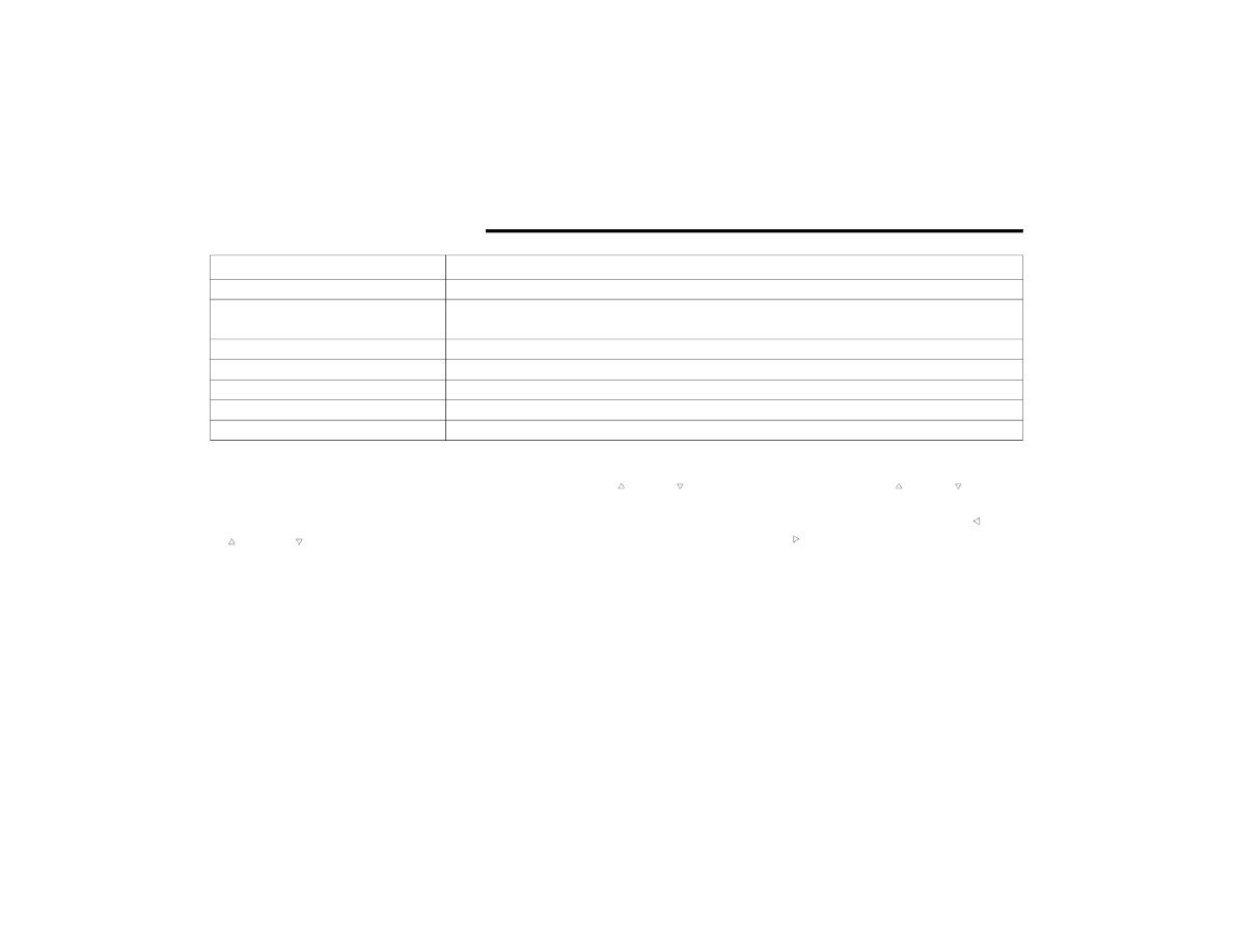
Setting

Instrument Cluster Display Message

None – With vehicle ignition ON

“KeySense in use. Max vehicle speed set to xx MPH/or km/h”

Max Vehicle Speed

“Max speed reached. KeySense in use” supported by a chime

“Approaching max speed xx MPH/km/h” supported by a chime

Start Up Fuel Alert message

“Range to empty xxx miles or km”

Early Low Fuel Alert Message

“Fuel Low”

ParkSense

“Feature cannot be disabled. KeySense in use”

Blind Spot

“Feature cannot be disabled. KeySense in use”

Forward Collision Warning

“Feature cannot be disabled. KeySense in use”

GETTING TO KNOW YOUR INSTRUMENT PANEL

89

Tire Pressure
If tire pressure is OK for all tires, a vehicle ICON is 

displayed with tire pressure values in each corner 

of the ICON.
If one or more tires have low pressure, “Inflate Tire 

To XX” is displayed with the vehicle ICON, and the 

tire pressure values in each corner of the ICON with 

the pressure value of the low tire displayed in a 

different color than the other tire pressure value.
If the Tire Pressure system requires service, 

“Service Tire Pressure System” is displayed.
Tire PSI is an information only function and cannot 

be reset  

Ú

page 171.

Coolant Temp
Displays the actual coolant temperature.
Transmission Temp
Displays the actual transmission temperature.
Oil Temp
Displays the actual oil temperature.

Oil Pressure
Displays the actual oil pressure.
Oil Life
Displays the remaining engine oil life as a 

percentage.
To reset the Oil Life, you must hold the OK button. 

The “Hold OK to Reset” instruction will be 

displayed at all times, but the following conditions 

will need to be met in order to reset Oil Life:

The ignition must be in the ON/RUN position

If the conditions are met, holding the OK button will 

reset the gauge and the numeric display will return 

to 100%.
If the conditions are not met, a pop-up message 

will display for five seconds, describing the 

required conditions, and then the Oil Life screen 

will reappear.
Battery Voltage
Displays the actual battery voltage.
Engine Hours — If Equipped
Displays the number of hours of engine operation.

Fuel Economy

Push and release the up  or down  arrow 

button until the Fuel Economy Menu item is 

highlighted in the instrument cluster display. The 

Fuel Economy Menu will display the following:

Two submenu pages that can be toggled 
between using the left  and right  arrow 

buttons; one with Current Value displayed and 

one without the Current Value displayed:

Average Fuel Economy

(MPG, L/100 km, or km/L)

Range To Empty (miles or km)

Current Fuel Economy 

(MPG, L/100 km, or km/L)

The Max and Min values will correspond to 

the particular engine requirements

Hold OK to reset average fuel economy 

information.

3

90

GETTING TO KNOW YOUR INSTRUMENT PANEL


Trip Info

Push and release the up  or down  arrow 

button until the Trip Menu item is highlighted in the 
instrument cluster display. Push the left  or 
right  arrow button to scroll through the Trip A 

and Trip B submenus. The Trip information will 

display the following:

Distance

Average Fuel Economy

Elapsed Time

Hold the OK button to reset feature information.

Stop / Start – If Equipped

Push and release the up  or down  arrow 

button until the Stop/Start menu title is displayed 

in the instrument cluster display.

Audio

Push and release the up  or down  arrow 

button until the Audio Menu displays in the 

instrument cluster display.

Messages

Push and release the up  or down  arrow 

button until Messages is highlighted in the 

instrument cluster display. This feature shows the 

number of stored warning messages. Pushing the 
right  arrow button will allow you to see what the 

stored messages are.

NOTE:

The pop-up messages indicate the status of the 

system and/or the conditions that need to be met. 

Messages remain in the stored stack until 

condition is cleared.

Screen Setup

Push and release the up  or down  arrow 

button until the Screen Setup Menu displays in the 

instrument cluster display. Push and release the 

OK button to enter the submenus. The Screen 

Setup feature allows you to change what 

information is displayed in the instrument cluster 

as well as the location that information is 

displayed.

GETTING TO KNOW YOUR INSTRUMENT PANEL

91

Base Instrument Cluster Display Screen Setup Options:

1 — Upper Left

None

Compass

Outside Temp

Time

Range

Current (MPG, L/100km, or km/L)

Average (MPG, L/100km, or km/L)

2 — Upper Right

None

Compass

Outside Temp

Time

Range

Current (MPG, L/100km, or km/L)

Average (MPG, L/100km, or km/L)

3

92

GETTING TO KNOW YOUR INSTRUMENT PANEL


3 — Center

None

Compass

Outside Temp

Time

Range

Average (MPG, L/100km, or km/L)

Current (MPG, L/100km, or km/L)

Trip A Distance

Trip B Distance

Audio Menu Title

Menu Title

Digital Speed

4 — Defaults

Restore

Cancel

Base Instrument Cluster Display Screen Setup Options:

GETTING TO KNOW YOUR INSTRUMENT PANEL

93

Speed Warning — If Equipped

Push and release the up  or down  arrow 

button until Speed Warning is highlighted in the 

instrument cluster display. Push and release the 
OK button to enter Speed Warning. Use the up  
or down  arrow button to turn the Speed Warning 

ON or OFF, then push and release the OK button to 

confirm the selection. If the ON status is selected, 
use the up  or down  arrow button to set the 

desired speed, then push the OK button to set the 

speed for the Speed Warning. A Speed Warning 

telltale will illuminate in the instrument cluster, 

with a number matching the set speed, with a 

pop-up message to inform the driver that the 

Speed Warning has been set to the desired speed. 

Each time the set speed is exceeded, a single 

chime will sound and a pop-up warning message 

will display. If the set speed is exceeded more than 

2 mph (3 km/h), a continuous chime will sound for 

up to 10 seconds, or until the speed is no longer 

exceeded. The telltale in the instrument cluster will 

also change from white to yellow, and a pop-up 

warning message will pop-up on the instrument 

cluster display.

NOTE:

Speed Warning is unavailable while KeySense is in 

use.

B

ATTERY

 S

AVER

 O

N

/B

ATTERY

 S

AVER


M

ODE

 M

ESSAGE

 — E

LECTRICAL

 L

OAD


R

EDUCTION

 A

CTIONS

 — I

F

 E

QUIPPED


This vehicle is equipped with an Intelligent Battery 

Sensor (IBS) to perform additional monitoring of 

the electrical system and status of the vehicle 

battery.
In cases when the IBS detects charging system 

failure, or the 12 Volt vehicle battery conditions are 

deteriorating, electrical load reduction actions will 

take place to extend the driving time and distance 

of the vehicle. This is done by reducing power to or 

turning off non-essential 12 Volt electrical loads. 

Load reduction will be functional when the vehicle 

propulsion system is active.
The vehicle may not be running depending on the 

High Voltage (HV) battery State Of Charge (SOC) or 

temperature. It will display a message if there is a 

risk of battery depletion to the point where the 

vehicle may stall due to lack of electrical supply, or 

will not restart after the current drive cycle.
When 12 Volt load reduction is activated, the 

message “Battery Saver On” or “Battery Saver 

Mode” will appear in the instrument cluster 

display.

These messages indicate the vehicle battery has a 

low state of charge and continues to lose electrical 

charge at a rate that the charging system cannot 

sustain.

NOTE:

The charging system is independent from load 

reduction. The charging system performs a diag

-

nostic on the charging system continuously.

If the Battery Charge Warning Light is on it may 

indicate a problem with the charging system  

Ú

page 95.

The electrical loads that may be switched off (if 

equipped), and vehicle functions which can be 

effected by load reduction:

Heated Seat/Vented Seats/Heated Wheel

Heated/Cooled Cup Holders — If Equipped

Rear Defroster And Heated Mirrors

HVAC System

115 Volts AC Power Inverter System

Audio and Telematics System

3

94

GETTING TO KNOW YOUR INSTRUMENT PANEL


Loss of the battery charge may indicate one or 

more of the following conditions:

The charging system cannot deliver enough 

electrical power to the vehicle system because 

the electrical loads are larger than the capability 

of charging system. The charging system is still 

functioning properly.

Turning on all possible vehicle electrical loads 

(e.g. HVAC to max settings, exterior and interior 

lights, overloaded power outlets +12 Volts, 

150W, USB ports) during certain driving condi

-

tions (city driving, towing, frequent stopping).

Installing options like additional lights, upfitter 

electrical accessories, audio systems, alarms 

and similar devices.

Unusual driving cycles (short trips separated by 

long parking periods).

The vehicle was parked for an extended period 

of time (weeks, months).

The battery was recently replaced and was not 

charged completely.

The battery was discharged by an electrical load 

left on when the vehicle was parked.

The battery was used for an extended period 

with the engine not running to supply radio, 

lights, chargers, +12 Volt portable appliances 

like vacuum cleaners, game consoles and 

similar devices.

What to do when an electrical load reduction 

action message is present (“Battery Saver On” or 

“Battery Saver Mode”)
During a trip:

Reduce power to unnecessary loads if possible:

Turn off redundant lights (interior or exte

-

rior)

Check what may be plugged in to power 

outlets +12 Volts, 150W, USB ports

Check HVAC settings (blower, temperature)

Check the audio settings (volume)

After a trip:

Check if any aftermarket equipment was 

installed (additional lights, upfitter electrical 

accessories, audio systems, alarms) and review 

specifications if any (load and Ignition Off Draw 

currents).

Evaluate the latest driving cycles (distance, 

driving time and parking time).

The vehicle should have service performed if 

the message is still present during consecutive 

trips and the evaluation of the vehicle and 

driving pattern did not help to identify the cause.

TRIP COMPUTER 

The Trip Computer is located in the instrument 
cluster display. Push and release the up  or 
down  arrow button until “Trip Info” is 

highlighted in the instrument cluster display. 

Navigate between Trip A or Trip B by using the 
right  and left  arrow buttons.
For each trip the following information will be 

displayed:
Trip A

Shows the total distance traveled for Trip A 

since the last reset.

Shows the Average MPG for Trip A since the last 

reset.

Shows the elapsed time traveled for Trip A since 

the last reset. Elapsed time will increment when 

the ignition switch is in the ON or START posi

-

tion.

GETTING TO KNOW YOUR INSTRUMENT PANEL

95

Trip B

Shows the total distance traveled for Trip B 

since the last reset.

Shows the Average MPG for Trip B since the last 

reset.

Shows the elapsed time traveled for Trip B since 

the last reset. Elapsed time will increment when 

the ignition switch is in the ON or START posi

-

tion.

To Reset A Trip Function
Push and hold the OK button to reset the currently 

displayed trip.

WARNING LIGHTS AND MESSAGES

The warning/indicator lights will illuminate in the 

instrument panel together with a dedicated 

message and/or acoustic signal when applicable. 

These indications are indicative and precautionary 

and as such must not be considered as exhaustive 

and/or alternative to the information contained in 

the Owner’s Manual, which you are advised to read 

carefully in all cases. Always refer to the 

information in this chapter in the event of a failure 

indication. All active warning/indicator lights will 

display first if applicable. The system check menu 

may appear different based upon equipment 

options and current vehicle status. Some warning/

indicator lights are optional and may not appear.

R

ED

 W

ARNING

 L

IGHTS

Air Bag Warning Light 

This warning light will illuminate to 

indicate a fault with the air bag, and will 

turn on for four to eight seconds as a bulb 

check when the ignition is placed in the 

ON/RUN or ACC/ON/RUN position. This light will 

illuminate with a single chime when a fault with the 

air bag has been detected, it will stay on until the 

fault is cleared. If the light is either not on during 

startup, stays on, or turns on while driving, have 

the system inspected at an authorized dealer as 

soon as possible.

Battery Charge Warning Light 

This warning light will illuminate when the 

battery is not charging properly. If it stays 

on while the engine is running, there may 

be a malfunction with the charging 

system. Contact an authorized dealer as soon as 

possible.
This indicates a possible problem with the 

electrical system or a related component.

Brake Warning Light 

This warning light monitors various brake 

functions, including brake fluid level and 

parking brake application. If the brake 

light turns on it may indicate that the 

parking brake is applied, that the brake fluid level 

is low, or that there is a problem with the Anti-Lock 

Brake System reservoir.
If the light remains on when the parking brake has 

been disengaged, and the fluid level is at the full 

mark on the master cylinder reservoir, it indicates 

a possible brake hydraulic system malfunction or 

that a problem with the Brake Booster has been 

detected by the Anti-Lock Brake System (ABS) / 

Electronic Stability Control (ESC) system. In this 

case, the light will remain on until the condition has 

been corrected. If the problem is related to the 

brake booster, the ABS pump will run when 

applying the brake, and a brake pedal pulsation 

may be felt during each stop.
The dual brake system provides a reserve braking 

capacity in the event of a failure to a portion of the 

hydraulic system. A leak in either half of the dual 

brake system is indicated by the Brake Warning 

Light, which will turn on when the brake fluid level 

in the master cylinder has dropped below a 

specified level.
The light will remain on until the cause is corrected.

NOTE:

The light may flash momentarily during sharp 

cornering maneuvers, which change fluid level 

conditions. The vehicle should have service 

performed, and the brake fluid level checked.
If brake failure is indicated, immediate repair is 

necessary.

3

96

GETTING TO KNOW YOUR INSTRUMENT PANEL


Vehicles equipped with the Anti-Lock Brake System 

(ABS) are also equipped with Electronic Brake 

Force Distribution (EBD). In the event of an EBD 

failure, the Brake Warning Light will turn on along 

with the ABS Light. Immediate repair to the ABS 

system is required.
Operation of the Brake Warning Light can be 

checked by turning the ignition switch from the OFF 

position to the ON/RUN position. The light should 

illuminate for approximately two seconds. The light 

should then turn off unless the parking brake is 

applied or a brake fault is detected. If the light does 

not illuminate, have the light inspected by an 

authorized dealer.
The light also will turn on when the parking brake 

is applied with the ignition switch in the ON/RUN 

position.

NOTE:

This light shows only that the parking brake is 

applied. It does not show the degree of brake appli

-

cation.

Door Open Warning Light — If Equipped  

This warning light will illuminate when a 

door is ajar/open and not fully closed. 

This indicator will reflect which doors are 

open.

NOTE:

If the vehicle is moving, there will also be a single 

chime.

Electric Power Steering (EPS) Fault 

Warning Light

This warning light will turn on when 

there's a fault with the EPS system  

Ú

page 116.

Electronic Throttle Control (ETC) Warning 

Light 

This warning light will illuminate to 

indicate a problem with the ETC system. 

If a problem is detected while the vehicle 

is running, the light will either stay on or 

flash depending on the nature of the problem. 

Cycle the ignition when the vehicle is safely and 

completely stopped and the transmission is placed 

in the PARK (P) position. The light should turn off. 

If the light remains on with the vehicle running, 

your vehicle will usually be drivable; however, see 

an authorized dealer for service as soon as 

possible.

NOTE:

This light may turn on if the accelerator and brake 

pedals are pressed at the same time.
If the light continues to flash when the vehicle is 

running, immediate service is required and you 

may experience reduced performance, an 

elevated/rough idle, or engine stall and your 

vehicle may require towing. The light will come on 

when the ignition is placed in the ON/RUN or ACC/

ON/RUN position and remain on briefly as a bulb 

check. If the light does not come on during starting, 

have the system checked by an authorized dealer.

WARNING!

Driving a vehicle with the red brake light on is 

dangerous. Part of the brake system may have 

failed. It will take longer to stop the vehicle. You 

could have a collision. Have the vehicle checked 

immediately.

WARNING!

Continued operation with reduced assist could 

pose a safety risk to yourself and others. Service 

should be obtained as soon as possible.

GETTING TO KNOW YOUR INSTRUMENT PANEL

97

Engine Coolant Temperature Warning 

Light 

This warning light warns of an 

overheated engine condition. If the 

engine coolant temperature is too high, 

this indicator will illuminate and a single 

chime will sound. If the temperature reaches the 

upper limit, a continuous chime will sound for four 

minutes or until the engine is able to cool; 

whichever comes first.
If the light turns on while driving, safely pull over 

and stop the vehicle. If the Air Conditioning (A/C) 

system is on, turn it off. Also, shift the transmission 

into NEUTRAL (N) and idle the vehicle. If the 

temperature reading does not return to normal, 

turn the engine off immediately and call for service  

Ú

page 237.

Hood Open Warning Light

This warning light will illuminate when the 

hood is left open and not fully closed.

NOTE:

If the vehicle is moving, there will also be a single 

chime.

Liftgate Open Warning Light  

This warning light will illuminate when the 

liftgate is open.

NOTE:

If the vehicle is moving, there will also be a single 

chime.

Oil Temperature Warning Light

This warning light will illuminate to 

indicate the engine oil temperature is 

high. If the light turns on while driving, 

stop the vehicle and shut off the engine 

as soon as possible. Wait for oil temperature to 

return to normal levels.

Oil Pressure Warning Light  

This warning light will illuminate to 

indicate low engine oil pressure. If the 

light turns on while driving, stop the 

vehicle, shut off the engine as soon as 

possible, and contact an authorized dealer. A 

chime will sound when this light turns on.
Do not operate the vehicle until the cause is 

corrected. This light does not indicate how much oil 

is in the engine. The engine oil level must be 

checked under the hood.

Seat Belt Reminder Warning Light 

This warning light indicates when the 

driver or passenger seat belt is 

unbuckled. When the ignition is first 

placed in the ON/RUN or ACC/ON/RUN 

position and if the driver’s seat belt is unbuckled, 

a chime will sound and the light will turn on. When 

driving, if the driver or front passenger seat belt 

remains unbuckled, the Seat Belt Reminder Light 

will flash or remain on continuously and a chime 

will sound  

Ú

page 174.

Transmission Temperature Warning Light 

— If Equipped

This warning light will illuminate to warn 

of a high transmission fluid temperature. 

This may occur with strenuous usage 

such as trailer towing. If this light turns 

on, stop the vehicle and run the engine at idle or 

slightly faster, with the transmission in PARK (P) or 

NEUTRAL (N), until the light turns off. Once the light 

turns off, you may continue to drive normally.

WARNING!

If you continue operating the vehicle when the 

Transmission Temperature Warning Light is 

illuminated you could cause the fluid to boil over, 

come in contact with hot engine or exhaust 

components and cause a fire.

3

98

GETTING TO KNOW YOUR INSTRUMENT PANEL


Vehicle Security Warning Light — 

If Equipped  

This warning light will flash at a fast rate 

for approximately 15 seconds when the 

vehicle security system is arming, and 

then will flash slowly until the vehicle is 

disarmed.

Y

ELLOW

 W

ARNING

 L

IGHTS

Anti-Lock Brake System (ABS) Warning 

Light 

This warning light monitors the ABS. The 

light will turn on when the ignition is 

placed in the ON/RUN or ACC/ON/RUN 

position and may stay on for as long as 

four seconds.

If the ABS light remains on or turns on while 

driving, then the Anti-Lock portion of the brake 

system is not functioning and service is required as 

soon as possible. However, the conventional brake 

system will continue to operate normally, 

assuming the Brake Warning Light is not also on.
If the ABS light does not turn on when the ignition 

is placed in the ON/RUN or ACC/ON/RUN position, 

have the brake system inspected by an authorized 

dealer.

Electronic Park Brake Warning Light

This warning light will illuminate to 

indicate the Electronic Park Brake is not 

functioning properly and service is 

required. Contact an authorized dealer.

Electronic Stability Control (ESC) Active 

Warning Light — If Equipped

This warning light will indicate when the 

ESC system is Active. The ESC Indicator 

Light in the instrument cluster will come 

on when the ignition is placed in the ON/

RUN or ACC/ON/RUN position, and when ESC is 

activated. It should go out with the engine running. 

If the ESC Indicator Light comes on continuously 

with the engine running, a malfunction has been 

detected in the ESC system. If this warning light 

remains on after several ignition cycles, and the 

vehicle has been driven several miles (kilometers) 

at speeds greater than 30 mph (48 km/h), see an 

authorized dealer as soon as possible to have the 

problem diagnosed and corrected.

The ESC OFF Indicator Light and the ESC Indi

-

cator Light come on momentarily each time the 

ignition is placed in the ON/RUN or ACC/ON/

RUN position.

The ESC system will make buzzing or clicking 

sounds when it is active. This is normal; the 

sounds will stop when ESC becomes inactive.

This light will come on when the vehicle is in an 

ESC event.

Electronic Stability Control (ESC) OFF 

Warning Light — If Equipped 

This warning light indicates the ESC is off. 

Each time the ignition is turned to 

ON/RUN or ACC/ON/RUN, the ESC 

system will be on, even if it was turned off 

previously.

CAUTION!

Continuous driving with the Transmission 

Temperature Warning Light illuminated will 

eventually cause severe transmission damage 

or transmission failure.

GETTING TO KNOW YOUR INSTRUMENT PANEL

99

Engine Check/Malfunction Indicator 

Warning Light

The Engine Check/Malfunction Indicator 

Light (MIL) is a part of an Onboard 

Diagnostic System called OBD II that 

monitors engine and automatic 

transmission control systems. This warning light 

will illuminate when the ignition is in the ON/RUN 

position before engine start. If the bulb does not 

come on when turning the ignition switch from OFF 

to ON/RUN, have the condition checked promptly.
Certain conditions, such as a loose or missing gas 

cap, poor quality fuel, etc., may illuminate the light 

after engine start. The vehicle should be serviced if 

the light stays on through several typical driving 

styles. In most situations, the vehicle will drive 

normally and will not require towing.
When the engine is running, the MIL may flash to 

alert serious conditions that could lead to 

immediate loss of power or severe catalytic 

converter damage. The vehicle should be serviced 

by an authorized dealer as soon as possible if this 

occurs.

Low Fuel Warning Light

When the fuel level reaches 

approximately 1.85 gal (7 L) this warning 

light will turn on, and remain on until fuel 

is added.

A single warning chime will sound with Low Fuel 

Warning.

Low Washer Fluid Warning Light — 

If Equipped

This warning light will illuminate when the 

windshield washer fluid is low.

Service Automatic Emergency Braking 

(AEB) Warning Light — If Equipped

This warning light will illuminate to 

indicate a fault in the AEB Warning 

System. Contact an authorized dealer for 

service  

Ú

page 168.

Service Stop/Start System Warning Light — 

If Equipped

This warning light will illuminate when the 

Stop/Start system is not functioning 

properly and service is required. Contact 

an authorized dealer for service  

Ú

page 117.

WARNING!

A malfunctioning catalytic converter, as 

referenced above, can reach higher 

temperatures than in normal operating 

conditions. This can cause a fire if you drive 

slowly or park over flammable substances such 

as dry plants, wood, cardboard, etc. This could 

result in death or serious injury to the driver, 

occupants or others.

CAUTION!

Prolonged driving with the Malfunction Indicator 

Light (MIL) on could cause damage to the 

vehicle control system. It also could affect fuel 

economy and driveability. If the MIL is flashing, 

severe catalytic converter damage and power 

loss will soon occur. Immediate service is 

required.

3

100

GETTING TO KNOW YOUR INSTRUMENT PANEL


Tire Pressure Monitoring System (TPMS) 

Warning Light 

The warning light switches on and a 

message is displayed to indicate that the 

tire pressure is lower than the 

recommended value and/or that slow 

pressure loss is occurring. In these cases, optimal 

tire duration and fuel consumption may not be 

guaranteed.
Should one or more tires be in the condition 

mentioned above, the display will show the 

indications corresponding to each tire.

Each tire, including the spare (if provided), should 

be checked monthly when cold and inflated to the 

inflation pressure recommended by the vehicle 

manufacturer on the vehicle placard or tire 

inflation pressure label. If your vehicle has tires of 

a different size than the size indicated on the 

vehicle placard or tire inflation pressure label, you 

should determine the proper tire inflation pressure 

for those tires.
As an added safety feature, your vehicle has been 

equipped with a TPMS that illuminates a low tire 

pressure light when one or more of your tires is 

significantly underinflated. Accordingly, when the 

low tire pressure light illuminates, you should stop 

and check your tires as soon as possible, and 

inflate them to the proper pressure. Driving on a 

significantly underinflated tire causes the tire to 

overheat and can lead to tire failure. Underinflation 

also reduces fuel efficiency and tire tread life, and 

may affect the vehicle’s handling and stopping 

ability.
Please note that the TPMS is not a substitute for 

proper tire maintenance, and it is the driver’s 

responsibility to maintain correct tire pressure, 

even if underinflation has not reached the level to 

trigger illumination of the TPMS low tire pressure 

light.
Your vehicle has also been equipped with a TPMS 

malfunction indicator to indicate when the system 

is not operating properly. The TPMS malfunction 

indicator is combined with the low tire pressure 

light. When the system detects a malfunction, the 

light will flash for approximately one minute and 

then remain continuously illuminated. This 

sequence will continue upon subsequent vehicle 

start-ups as long as the malfunction exists. When 

the malfunction indicator is illuminated, the 

system may not be able to detect or signal low tire 

pressure as intended. TPMS malfunctions may 

occur for a variety of reasons, including the 

installation of replacement or alternate tires or 

wheels on the vehicle that prevent the TPMS from 

functioning properly. Always check the TPMS 

malfunction light after replacing one or more tires 

or wheels on your vehicle to ensure that the 

replacement or alternate tires and wheels allow 

the TPMS to continue to function properly.

CAUTION!

Do not continue driving with one or more flat 

tires as handling may be compromised. Stop the 

vehicle, avoiding sharp braking and steering. If a 

tire puncture occurs, repair immediately using 

the dedicated tire repair kit and contact an 

authorized dealer as soon as possible.

CAUTION!

The TPMS has been optimized for the original 

equipment tires and wheels. TPMS pressures 

and warning have been established for the tire 

size equipped on your vehicle. Undesirable 

system operation or sensor damage may result 

when using replacement equipment that is not 

of the same size, type, and/or style. Aftermarket 

wheels can cause sensor damage. Using 

aftermarket tire sealants may cause the Tire 

Pressure Monitoring System (TPMS) sensor to 

become inoperable. After using an aftermarket 

tire sealant it is recommended that you take 

your vehicle to an authorized dealer to have your 

sensor function checked.

GETTING TO KNOW YOUR INSTRUMENT PANEL

101

Y

ELLOW

 I

NDICATOR

 L

IGHTS

Automatic Emergency Braking (AEB) OFF 

Indicator Light — If Equipped

This indicator light illuminates to indicate 

that Forward Collision Warning is off.

G

REEN

 I

NDICATOR

 L

IGHTS

Cruise Control Set Indicator Light —

If Equipped  

This indicator light will illuminate when 

the cruise control is set to the desired 

speed  

Ú

page 119.

Front Fog Indicator Light — If Equipped

This indicator light will illuminate when 

the front fog lights are on.

KeySense Indicator Light — If Equipped

The KeySense indicator is illuminated 

when a KeySense key is detected upon 

startup of the vehicle. The indicator will 

remain lit for the entire key cycle as a 

reminder that the KeySense key is in use. While 

the KeySense key is in use, the vehicle will respond 

to settings associated with the KeySense profile  

Ú

page 12.

Parking/Headlight On Indicator Light 

This indicator light will illuminate when 

the park lights or headlights are turned 

on.

Stop/Start Active Indicator Light —

If Equipped

This indicator light will illuminate when 

the Stop/Start function is in “Autostop” 

mode  

Ú

page 117.

Turn Signal Indicator Lights  

When the left or right turn signal is 

activated, the turn signal indicator will 

flash independently and the 

corresponding exterior turn signal lamps 

will flash. Turn signals can be activated when the 

multifunction lever is moved down (left) or up 

(right).

NOTE:

A continuous chime will sound if the vehicle is 

driven more than 1 mile (1.6 km) with either 

turn signal on.

Check for an inoperative outside light bulb if 

either indicator flashes at a rapid rate.

W

HITE

 I

NDICATOR

 L

IGHTS

Cruise Control Ready Indicator Light 

This indicator light will illuminate when 

the cruise control is ready, but not set  

Ú

page 119.

Set Speed Display

The Set Speed Display indicator light 

indicates the set speed for the Cruise 

Control.

B

LUE

 I

NDICATOR

 L

IGHTS

High Beam Indicator Light

This indicator light will illuminate to 

indicate that the high beam headlights 

are on. With the low beams activated, 

push the multifunction lever forward 

(toward the front of the vehicle) to turn on the high 

beams. Pull the multifunction lever rearward 

(toward the rear of the vehicle) to turn off the high 

beams. If the high beams are off, pull the lever 

toward you for a temporary high beam on, “flash to 

pass” scenario.

3

102

GETTING TO KNOW YOUR INSTRUMENT PANEL


ONBOARD DIAGNOSTIC SYSTEM — OBD II  

Your vehicle is equipped with a sophisticated 

Onboard Diagnostic system called OBD II. This 

system monitors the performance of the 

emissions, engine, and automatic transmission 

control systems. When these systems are 

operating properly, your vehicle will provide 

excellent performance and fuel economy, as well 

as emissions well within current government 

regulations.
If any of these systems require service, the OBD II 

system will turn on the Malfunction Indicator Light 

(MIL). It will also store diagnostic codes and other 

information to assist your service technician in 

making repairs. Although your vehicle will usually 

be drivable and not need towing, see an authorized 

dealer for service as soon as possible.

O

NBOARD

 D

IAGNOSTIC

 S

YSTEM


(OBD II) C

YBERSECURITY

Your vehicle is required to have OBD II and a 

connection port to allow access to information 

related to the performance of your emissions 

controls. Authorized service technicians may need 

to access this information to assist with the 

diagnosis and service of your vehicle and 

emissions system  

Ú

page 140.

CAUTION!

Prolonged driving with the MIL on could cause 

further damage to the emission control 

system. It could also affect fuel economy and 

driveability. The vehicle must be serviced 

before any emissions tests can be performed.

If the MIL is flashing while the vehicle is 

running, severe catalytic converter damage 

and power loss will soon occur. Immediate 

service is required.

WARNING!

ONLY an authorized service technician should 

connect equipment to the OBD II connection 

port in order to read the VIN, diagnose, or 

service your vehicle.

If unauthorized equipment is connected to the 

OBD II connection port, such as a 

driver-behavior tracking device, it may:

Be possible that vehicle systems, 

including safety related systems, could be 

impaired or a loss of vehicle control could 

occur that may result in an accident 

involving serious injury or death.

Access, or allow others to access, infor

-

mation stored in your vehicle systems, 

including personal information.

GETTING TO KNOW YOUR INSTRUMENT PANEL

103

EMISSIONS INSPECTION AND 

MAINTENANCE PROGRAMS   

In some localities, it may be a legal requirement to 

pass an inspection of your vehicle's emissions 

control system. Failure to pass could prevent 

vehicle registration.

For states that require an Inspection and 

Maintenance (I/M), this check verifies 

the Malfunction Indicator Light (MIL) is 

functioning and is not on when the 

engine is running, and that the OBD II system is 

ready for testing.
Normally, the OBD II system will be ready. The 

OBD II system may not be ready if your vehicle was 

recently serviced, recently had a depleted battery 

or a battery replacement. If the OBD II system 

should be determined not ready for the I/M test, 

your vehicle may fail the test.
Your vehicle has a simple ignition actuated test, 

which you can use prior to going to the test station. 

To check if your vehicle's OBD II system is ready, 

you must do the following:

1. Cycle the ignition switch to the ON position, 

but do not crank or start the engine.

NOTE:

If you crank or start the engine, you will have to 

start this test over.
2. As soon as you cycle the ignition switch to the 

ON position, you will see the Malfunction 

Indicator Light (MIL) symbol come on as part of 

a normal bulb check.

3. Approximately 15 seconds later, one of two 

things will happen:

The MIL will flash for about 10 seconds and 

then return to being fully illuminated until 

you turn OFF the ignition or start the engine. 

This means that your vehicle's OBD II 

system is not ready and you should not 

proceed to the I/M station.

The MIL will not flash at all and will remain 

fully illuminated until you place the ignition 

in the off position or start the engine. This 

means that your vehicle's OBD II system is 

ready and you can proceed to the I/M 

station.

If your OBD II system is not ready, you should see 

an authorized dealer or repair facility. If your 

vehicle was recently serviced or had a battery 

failure or replacement, you may need to do nothing 

more than drive your vehicle as you normally would 

in order for your OBD II system to update. A 

recheck with the above test routine may then 

indicate that the system is now ready.
Regardless of whether your vehicle's OBD II system 

is ready or not, if the MIL is illuminated during 

normal vehicle operation you should have your 

vehicle serviced before going to the I/M station. 

The I/M station can fail your vehicle because the 

MIL is on with the engine running.

3


Content      ..     4      5      6      7     ..