Chrysler PT Cruiser. Manual - part 920


  Index      Chrysler     Chrysler PT Cruiser - service repair manual 2005 year


Search            


Content   ..  918  919  920  921   ..


Chrysler PT Cruiser. Manual - part 920


LATCH STRIKER

REMOVAL

(1) Open liftgate.
(2) Mark outline of striker on sill to aid installa-

tion.

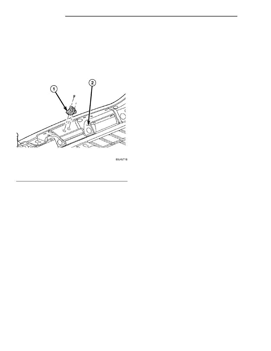
(3) Remove screws attaching striker to sill (Fig. 7).
(4) Remove striker from vehicle.

INSTALLATION

(1) Place striker in position on vehicle (Fig. 7).
(2) Align striker to outline mark on sill.
(3) Install screws attaching striker to sill. Tighten

screws to 28 N·m (21 ft. lbs.) torque.

(4) Verify liftgate alignment and operation.

LIFTGATE

REMOVAL

(1) Release liftgate latch and open liftgate.
(2) Remove screws attaching liftgate wire connec-

tor to rear header.

(3) Disconnect liftgate wire harness from body

wire harness.

(4) Remove liftgate upper frame molding.
(5) Disconnect rear window washer hose from

spray nozzle.

(6) Support liftgate on a suitable lifting device.
(7) Remove screws attaching support cylinders to

liftgate.

(8) Remove bolts attaching liftgate hinge to roof

header (Fig. 8).

(9) With assistance, remove liftgate from vehicle.

INSTALLATION

(1) With assistance, place liftgate in position on

vehicle.

(2) Install bolts attaching liftgate hinge to roof

header. Tighten bolts to 33 N·m (24 ft. lbs.) torque
(Fig. 8).

(3) Install screws attaching support cylinders to

liftgate. Tighten bolts to 28 N·m (21 ft. lbs.) torque.

(4) Remove lifting device from under liftgate.
(5) Connect liftgate wire harness into body wire

harness.

(6) Install screws attaching wire connector to rear

header.

(7) Connect rear window washer hose onto spray

nozzle.

(8) Install liftgate upper frame molding.

Fig. 7 LIFTGATE LATCH STRIKER

1 - LIFTGATE LATCH STRIKER
2 - LIFTGATE OPENING LOWER CENTER PANEL

23 - 138

LIFTGATE

PT

(9) Verify liftgate alignment. The liftgate should

have a gap to adjacent panels and fit flush across the
gaps. The gap is;

• 7 mm (0.280 in.) to the fascia,

• 6 mm (0.240 in.) to the roof,

• 4 mm (0.160 in.) to the aperture.

LIFTGATE LOCK CYLINDER

REMOVAL

NOTE: Do not remove E-clip.

(1) Remove outside liftgate handle.
(2) Remove lock cylinder clip from handle (Fig. 9).
(3) Remove lock cylinder and arm from handle.

INSTALLATION

(1) Install lock cylinder clip into liftgate (Fig. 9).
(2) Push lock cylinder into handle until clip

engages groove in lock cylinder with an audible click.

(3) Install outside liftgate handle.
(4) Verify lock cylinder operation.

LIFTGATE SUPPORT ROD

REMOVAL

(1) Release liftgate latch and open liftgate.
(2) Support liftgate on a suitable lifting device in

the full open position.

(3) Pull liftgate opening weatherstrip from D-pillar

flange next to prop assembly end pivot.

(4) Remove bolt attaching end pivot to D-pillar

(Fig. 10).

(5) Remove bolt attaching prop assembly to lift-

gate.

(6) Remove prop assembly from vehicle.

INSTALLATION

Ensure that the cylinder end is attached to the

D-pillar and the shaft end is attached to the liftgate
(Fig. 10).

Fig. 8 LIFTGATE

1 - EDGE OF LIFTGATE TROUGH

5 - LIFTGATE TRIM PANEL

2 - LIFTGATE HALO

6 - LIFTGATE PULL CUP

3 - LIFTGATE

7 - REAR CONVENIENCE BEZEL

4 - CHMSL COVER TRIM

Fig. 9 LOCK CYLINDER REMOVAL

1 - LIFTGATE HANDLE
2 - LIFTGATE LOCK CYLINDER

PT

LIFTGATE

23 - 139

LIFTGATE (Continued)

(1) Place prop assembly position.
(2) Install bolt attaching prop assembly to liftgate.
(3) Install bolt attaching end pivot to D-pillar.

Tighten bolts to 28 N·m (21 ft. lbs.) torque.

(4) Install liftgate opening weatherstrip to D-pillar

flange next to prop assembly end pivot.

(5) Close liftgate. Check liftgate operation.

LIFTGATE TRIM PANEL

REMOVAL

(1) Open liftgate.
(2) Using a trim stick (C-4755), disengage clips

attaching CHMSL cover trim to liftgate (Fig. 1).

(3) Remove CHMSL cover trim from vehicle.
(4) Using a trim stick (C-4755), disengage clips

attaching liftgate halo trim panels both sides (Fig. 8).

(5) Remove halo trim panels trim from vehicle.
(6) Using a trim stick (C-4755), disengage clips

attaching liftgate trim panel (Fig. 8).

(7) Remove liftgate trim panel trim from vehicle.

INSTALLATION

(1) Place liftgate trim panel in position on vehicle

(Fig. 8).

(2) Press tabs into position to attaching liftgate

trim panel to liftgate.

(3) Place liftgate halo trim panels in position on

vehicle, both sides (Fig. 8).

(4) Press tabs into position to attaching liftgate

halo trim panels to liftgate.

(5) Place CHMSL cover trim in position on vehicle

(Fig. 1).

(6) Press tabs into position to hold CHMSL cover

trim to liftgate.

(7) Close liftgate.

Fig. 10 LIFTGATE PROP ASSEMBLY

1 - LIFTGATE GAS PROP ROD
2 - LIFTGATE ASSEMBLY

3 - LIFTGATE SIDE DRAIN TROUGH
4 - DRAIN TROUGH OUTER STABLE BUMPER

23 - 140

LIFTGATE

PT

LIFTGATE SUPPORT ROD (Continued)

PAINT

TABLE OF CONTENTS

page

page

PAINT

SPECIFICATIONS - COLOR CODES

. . . . . . . . 141

BASECOAT/CLEARCOAT FINISH

DESCRIPTION

. . . . . . . . . . . . . . . . . . . . . . . . 142

PAINT CODE

DESCRIPTION

. . . . . . . . . . . . . . . . . . . . . . . . 142

PAINT TOUCH-UP

DESCRIPTION

. . . . . . . . . . . . . . . . . . . . . . . . 142

FINESSE SANDING/BUFFING & POLISHING

DESCRIPTION

. . . . . . . . . . . . . . . . . . . . . . . . 142

PAINT

SPECIFICATIONS - COLOR CODES

EXTERIOR COLORS

EXTERIOR COLOR

DAIMLERCHRYSLER

CODE

EXTERIOR COLOR

DAIMLERCHRYSLER

CODE

BLACK CLEAR COAT

DX8

FLAME RED CLEAR COAT

PR4

BRIGHT SILVER METALLIC

CLEAR COAT

WS2

INFERNO RED TINTED

PEARL COAT

WEL

COOL VANILLA CLEAR

COAT

XWG

LINEN GOLD PEARL COAT

ZKJ

DEEP PLUM PEARL COAT

WHP

MIDNIGHT BLUE PEARL

COAT

BB8

DEEP LAVA RED PEARL

COAT

ZMQ

INTERIOR COLORS

INTERIOR COLOR

DAIMLERCHRYSLER

COLOR CODE

INTERIOR COLOR

DAIMLERCHRYSLER

COLOR CODE

DARK SLATE GRAY

DV

LIGHT PEARL BEIGE/DARK

TAUPE

FL

PT

PAINT

23 - 141


Content   ..  918  919  920  921   ..