Chrysler PT Cruiser. Manual - part 884
 

  Index      Chrysler     Chrysler PT Cruiser - service repair manual 2005 year


Search            


Content   ..  882  883  884  885   ..


Chrysler PT Cruiser. Manual - part 884


STANDARD PROCEDURE

STANDARD PROCEDURE - TIRE INFLATION
PRESSURES

The specified tire pressures have been chosen to

provide safe operation, vehicle stability, and a smooth
ride. The proper tire pressure specification can be
found on the Tire Inflation Pressure Label provided
with the vehicle (usually on the driver’s side B-pil-
lar).

A quality air pressure gauge is recommended to

check tire air pressure. Tire pressure should be
checked cold once per month. Check tire pressure
more frequently when the weather temperature var-
ies widely. Tire pressure will decrease when the out-
door temperature drops. After checking the air
pressure, replace valve cap finger tight.

Inflation pressures specified on the Tire Inflation

Pressure Label are always the cold inflation pressure
of the tire. Cold inflation pressure is obtained after
the vehicle has not been operated for at least 3
hours, or the vehicle is driven less than one mile
after being inoperative for 3 hours. Tire inflation
pressures may increase from 2 to 6 pounds per
square inch (psi) during operation. Do not reduce this
normal pressure buildup.

Improper inflation can cause:
• Uneven wear patterns

• Reduced tread life

• Reduced fuel economy

• Unsatisfactory ride

• The vehicle to drift.

WARNING: OVER OR UNDER INFLATED TIRES CAN
AFFECT VEHICLE HANDLING. THE TIRE CAN FAIL
SUDDENLY, RESULTING IN LOSS OF VEHICLE
CONTROL.

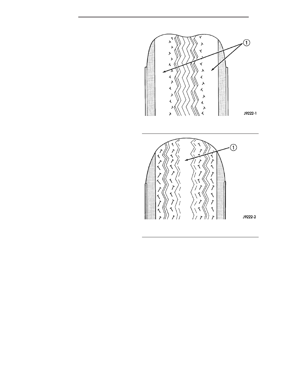
Under inflation causes rapid shoulder wear, tire

flexing, and can result in tire failure (Fig. 19).

Over inflation causes rapid center wear and loss of

the tire’s ability to cushion shocks (Fig. 20).

STANDARD PROCEDURE - TIRE PRESSURE
FOR HIGH SPEED OPERATION

DaimlerChrysler Corporation advocates driving at

safe speeds within posted speed limits. Where speed
limits allow the vehicle to be driven at high speeds,
correct tire inflation pressure is very important.
Vehicles loaded to maximum capacity should not be
driven at continuous speeds over 120 km/h (75 mph).
Never exceed the maximum speed capacity of the
tire. For information on tire identification and speed
ratings, (Refer to 22 - TIRES/WHEELS/TIRES -
DESCRIPTION).

Fig. 19 Under Inflation Wear

1 - THIN TIRE TREAD AREAS

Fig. 20 Over Inflation Wear

1 - THIN TIRE TREAD AREA

22 - 12

TIRES/WHEELS

PT

TIRES (Continued)

STANDARD PROCEDURE - TIRE LEAK
REPAIRING

For proper repairing, a radial tire must be removed

from the wheel. Repairs should only be made if the
defect, or puncture, is in the tread area (Fig. 21). The
tire should be replaced if the puncture is located in
the sidewall.

Deflate tire completely before attempting to dis-

mount the tire from the wheel. Use a lubricant
such as a mild soap solution when dismounting
or mounting tire. 
Use tools free of burrs or sharp
edges which could damage the tire or wheel rim.

Before mounting tire on wheel, make sure all rust

is removed from the rim bead and repaint if neces-
sary.

Install wheel on vehicle, and progressively tighten

the 5 wheel nuts to a torque of 135 N·m (100 ft. lbs.).

CLEANING - TIRES

Before delivery of a vehicle, remove the protective

coating on the tires with white sidewalls or raised
white letters. To remove the protective coating, apply
warm water and let it soak for a few minutes. After-
wards, scrub the coating away with a soft bristle
brush. Steam cleaning may also be used to remove
the coating.

CAUTION: DO NOT use gasoline, mineral oil, oil-
based solvent or a wire brush for cleaning.

WHEELS

DESCRIPTION - WHEEL

Original equipment wheels are designed for proper

operation at all loads up to the specified maximum
vehicle capacity.

All models use steel or cast aluminum drop center

wheels. Every wheel has raised sections between the
rim flanges and rim drop well called safety humps
(Fig. 22).

Initial inflation of the tires forces the bead over

these raised sections. In case of air loss the raised
sections help hold the tire in position on the wheel
until the vehicle can be brought to a safe stop.

Cast aluminum wheels require special balance

weights to fit the contour of the wheel flange (Fig.
23).

The wheel mounting studs and nuts are designed

for specific wheel applications and must be replaced
with equivalent parts. Do not use replacement parts
of lesser quality or of a substitute design. All alumi-
num wheels use wheel mounting nuts with an
enlarged nose. This enlarged nose is necessary to
ensure proper retention of the wheels.

Vehicles that are equipped with bolt-on wheel cov-

ers use the wheel mounting nuts to retain the wheel
cover.

Fig. 21 Tire Repair Area

1 - REPAIRABLE AREA

Fig. 22 Safety Rim

1 - TIRE
2 - WELL
3 - SAFETY HUMPS
4 - FLANGE

PT

TIRES/WHEELS

22 - 13

TIRES (Continued)

DIAGNOSIS AND TESTING - WHEEL
INSPECTION

Inspect wheels for:
• Excessive runout

• Dents, cracks or irregular bends

• Damaged wheel stud (lug) holes

• Air Leaks

NOTE: Do not attempt to repair a wheel by hammer-
ing, heating or welding.

If a wheel is damaged, an original equipment

replacement wheel should be used. When obtaining
replacement wheels, they must be equivalent in load
carrying capacity. The diameter, width, offset, pilot
hole and bolt circle of the wheel should be the same
as the original wheel.

WARNING:

FAILURE

TO

USE

EQUIVALENT

REPLACEMENT

WHEELS

MAY

ADVERSELY

AFFECT THE SAFETY AND HANDLING OF THE
VEHICLE.

WARNING: REPLACEMENT WITH USED WHEELS IS
NOT RECOMMENDED. THE SERVICE HISTORY OF
THE WHEEL MAY HAVE INCLUDED SEVERE TREAT-
MENT OR VERY HIGH MILEAGE. THE RIM COULD
FAIL WITHOUT WARNING.

CLEANING

WHEEL AND WHEEL TRIM CARE

All wheels and wheel trim, especially aluminum

and chrome plated, should be cleaned regularly using
mild soap and water to maintain their luster and to
prevent corrosion. Wash them with the same soap
solution recommended for the body of the vehicle.

When cleaning extremely dirty wheels, care must

be taken in the selection of tire and wheel cleaning
chemicals and equipment to prevent damage to the
wheels. Mopar

t Wheel Treatment or Mopart Chrome

Cleaner is recommended. Any of the “DO NOT USE”
items listed below can damage wheels and wheel
trim.

DO NOT USE:
• Any abrasive cleaner

• Any abrasive cleaning pad (such as steel wool)

or abrasive brush

• Any cleaner that contains an acid which can

react with and discolor the chrome surface. Many
wheel cleaners contain acids that can harm the
wheel surface.

• Oven cleaner

• A car wash that uses carbide-tipped wheel clean-

ing brushes or acidic solutions.

SPECIFICATIONS

WHEEL

SPECIFICATIONS

DESCRIPTION

SPECIFICATION

Wheel Mounting (Lug)
Nut Hex Size

19 mm

Wheel Mounting Stud
Size

M12 x 1.5 mm

TORQUE SPECIFICATIONS

DESCRIPTION

N·m

Ft.

Lbs.

In.

Lbs.

Wheel Mounting (Lug ) Nut

135

100

Fig. 23 Aluminum Wheel Weight

1 - TIRE
2 - WHEEL
3 - STYLED WHEEL WEIGHT

22 - 14

TIRES/WHEELS

PT

WHEELS (Continued)

WHEEL COVER

REMOVAL

(1) Raise the vehicle. (Refer to LUBRICATION &

MAINTENANCE/HOISTING - STANDARD PROCE-
DURE)

CAUTION: When removing the bolt-on wheel cover,
do not attempt to pry the wheel cover off the wheel.

(2) Unthread and remove the 5 nuts attaching the

wheel and wheel cover to the vehicle (Fig. 24).

(3) Remove the wheel cover using care not to let

the tire and wheel assembly fall off the vehicle.

INSTALLATION

CAUTION: Installing the wheel mounting nuts with-
out having good metal-to-mental contact between
the back of the wheel and the hub mounted brake
disc or drum could cause the wheel to bind and
eventually cause loosening of the wheel mounting
nuts.

CAUTION: Never use oil or grease on wheel studs
or wheel mounting nuts.

(1) With the tire and wheel assembly positioned on

the wheel studs without the wheel mounting nuts
installed, align the valve notch in the wheel cover
with the valve stem on the wheel and install the
wheel cover on the hub mounted studs.

(2) Install and lightly tighten the wheel mounting

nuts in the proper sequence (Fig. 25).

(3) Lower the vehicle.

(4) Progressively tighten the 5 wheel mounting

nuts in the proper sequence until tightened to half of
the specified torque (Fig. 25). Finally, tighten the
wheel mounting nuts in the proper sequence to 135
N·m (100 ft. lbs.) torque.

WHEEL MOUNTING STUDS -
FRONT

REMOVAL

Use the following procedure to remove and install

one of five studs on one wheel hub.

(1) Raise the vehicle. Refer to Hoisting in Lubrica-

tion And Maintenance.

(2) Remove the front tire and wheel assembly.
(3) Remove the two guide pin bolts securing the

front disc brake caliper to the steering knuckle (Fig.
26).

(4) Remove the disc brake caliper from the steer-

ing knuckle. The caliper is removed by first tipping
either the top (right side) or bottom (left side) of the
caliper away from the brake rotor, then pulling the
caliper off the opposite end’s caliper slide abutment
(on the knuckle) and rotor.

(5) Hang the caliper out of the way using a wire

hanger or cord. Do not support the caliper by letting
it hang by the hydraulic hose.

(6) Remove any retainer clips from the wheel

mounting studs. Remove the brake rotor from the
front hub (Fig. 26).

CAUTION: Do not hammer wheel mounting studs
out of the hub. Damage to the wheel bearing will
occur, leading to premature bearing failure.

Fig. 24 Wheel And Cover Mounting

1 - WHEEL MOUNTING NUTS
2 - BOLT-ON WHEEL COVER

Fig. 25 Nut Tightening Sequence

1 - BOLT-ON WHEEL COVER

PT

TIRES/WHEELS

22 - 15


Content   ..  882  883  884  885   ..