Chrysler PT Cruiser. Manual - part 771


  Index      Chrysler     Chrysler PT Cruiser - service repair manual 2005 year


Search            


Content   ..  769  770  771  772   ..


Chrysler PT Cruiser. Manual - part 771


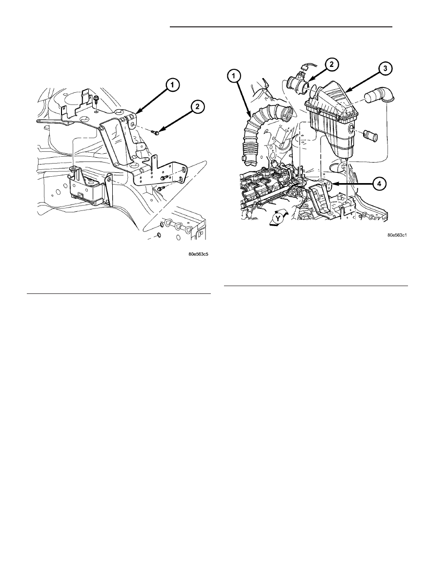
(19) Install PDC/air cleaner assembly bracket (Fig.

97).

(20) Install PDC into position.
(21) Install air cleaner assembly (Fig. 98).

(22) Connect battery negative cable.

Fig. 97 Air Cleaner/PDC Bracket

1 - BRACKET
2 - BOLT (4)

Fig. 98 Air Cleaner Assembly

1 - DUCT
2 - MASS AIR FLOW SENSOR
3 - AIR CLEANER ASSEMBLY
4 - BRACKET

21 - 38

G288 MANUAL TRANSAXLE

PT

G288 MANUAL TRANSAXLE (Continued)

INSTALLATION—2.4L TURBO

(1) Install transaxle to transmission jack and

secure. Raise transaxle into position and install to
engine.

(2) Install accessible bellhousing-to-block bolts and

torque to 108 N·m (80 ft. lbs.) torque (Fig. 99).

(3) Install four (4) modular clutch-to-driveplate

bolts. Align drive plate and modular clutch alignment
marks placed upon disassembly. Start with tight-tol-
erance (slotted) hole (Fig. 100), install and torque
bolts to 88 N·m (65 ft. lbs.) torque.

Fig. 99 Transaxle Removal/Installation

1 - BOLT (4)

2 - G288 TRANSAXLE

Fig. 100 Modular Clutch-to-Driveplate Bolts

1 - DRIVEPLATE
2 - MODULAR CLUTCH ASSEMBLY
3 - TIGHT TOLERANCE HOLE
4 - BOLT (4)

PT

G288 MANUAL TRANSAXLE

21 - 39

G288 MANUAL TRANSAXLE (Continued)

(4) Install transaxle upper mount bracket (Fig.

101).

(5) Raise transaxle with jack until mount bracket

pilots into upper mount. Access engine compartment.
Install and torque upper mount-to-transaxle bracket
bolts (Fig. 102).

(6) Remove transmission jack.
(7) Install starter motor into position. Install

ground cable and lower starter mounting bolt (Fig.
103).

(8) Install lower bellhousing bolt.
(9) Install two (2) intercooler connector pipe-to-en-

gine oil pan bolts (Fig. 104).

Fig. 101 Transaxle Upper Mount Bracket

1 - TRANSAXLE
2 - BRACKET
3 - BOLT

Fig. 102 Upper Mount-to-Bracket

1 - BOLT (2)
2 - MOUNT
3 - BRACKET

Fig. 103 Starter Bolt and Ground Cable

1 - GROUND CABLE
2 - BOLT
3 - STARTER MOTOR

Fig. 104 Intercooler Inlet Hose Fasteners

1 - INTERCOOLER INLET HOSE
2 - SCREW (2)
3 - STRUCTURAL COLLAR

21 - 40

G288 MANUAL TRANSAXLE

PT

G288 MANUAL TRANSAXLE (Continued)

(10) Remove transaxle fill plug and add suitable

amount of ATF+4 (Automatic Transmission Fluid—
Type 9602). Torque fill plug to 39-47 N·m (29-35 ft.
lbs.). (Refer to 21 - TRANSMISSION/TRANSAXLE/
MANUAL/FLUID - STANDARD PROCEDURE)

(11) Install intermediate shaft/bearing assembly

into position. Install and torque bearing-to-retainer
bolts (Fig. 105).

(12) Install halfshafts (Refer to 3 - DIFFEREN-

TIAL & DRIVELINE/HALF SHAFT - INSTALLA-
TION).

(13) Lower vehicle.
(14) Connect clutch hydraulic plumbing to slave

cylinder quick-connect (Fig. 106). An audible “click”
should be heard. Verify connection by pulling out-
ward.

(15) Connect vehicle speed sensor connector (Fig.

107).

(16) Connect back-up lamp switch connector (Fig.

107).

(17) Install gearshift cable bracket and torque

bolts (Fig. 108).

Fig. 105 Halfshaft and Intermediate Shaft

1 - HALFSHAFT (LH)
2 - TRANSAXLE
3 - BOLT

4 - INTERMEDIATE SHAFT
5 - HALFSHAFT (RH)
6 - BOLT (2)

Fig. 106 Clutch Slave Cylinder Hydraulic

Connection

1 - MASTER CYLINDER TUBE
2 - SLAVE CYLINDER

PT

G288 MANUAL TRANSAXLE

21 - 41

G288 MANUAL TRANSAXLE (Continued)


Content   ..  769  770  771  772   ..