Chrysler PT Cruiser. Manual - part 464


  Index      Chrysler     Chrysler PT Cruiser - service repair manual 2005 year


Search            


Content   ..  462  463  464  465   ..


Chrysler PT Cruiser. Manual - part 464


(9) Remove radiator assembly (Fig. 36) by lifting it

up from the engine compartment. Care should be
taken not to damage the cooling fins and tubes
during removal.

(10) Non-Turbo Vehicles: Remove the lower air

seal from radiator (Fig. 34).

CLEANING

Clean radiator fins are necessary for good heat

transfer. The radiator and air conditioning fins
should be cleaned when an accumulation of debris

has occurred. With the engine cold, apply cold water
and compressed air to the back (engine side) of the
radiator to flush the radiator and/or A/C condenser of
debris.

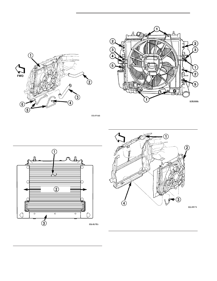
Fig. 33 Radiator Hose Connections

1 - RADIATOR
2 - RADIATOR UPPER HOSE
3 - RADIATOR LOWER HOSE
4 - CLAMP
5 - TRANSMISSION OIL COOLER HOSES
6 - CLAMP

Fig. 34 Air Seals

1 - A/C CONDENSER
2 - SIDE AIR SEALS
3 - LOWER AIR SEAL

Fig. 35 Cooling Module Fasteners - 2.4L Turbo

1 - RADIATOR FAN FASTENERS
2 - CONDENSER FASTENERS
3 - TRANSMISSION OIL COOLER FASTENERS
4 - RADIATOR FAN/CONDENSER FASTENER
5 - CHARGE AIR COOLER FASTENERS

Fig. 36 Cooling Module Assembly

1 - UPPER RADIATOR CLOSURE PANEL
2 - COOLING MODULE
3 - RADIATOR FAN CONNECTOR
4 - LOWER RADIATOR CROSSMEMBER

7 - 58

ENGINE - 2.0/2.4L DOHC

PT

RADIATOR (Continued)

INSPECTION

Inspect the radiator tanks for cracks, broken or

missing fittings also inspect the joint where the
tanks seam up to the radiator core for signs of leak-
age and/or deteriorating seals.

Inspect radiator core for corroded, bent or missing

cooling fins. Inspect the core for bent or damaged
cooling tubes.

INSTALLATION

(1) Non-Turbo Vehicles: Install the lower air seal

to radiator (Fig. 34).

NOTE: Turbocharger Equipped Vehicles: When low-
ering

radiator,

make

sure

lower

radiator

pins

engage properly through charge air cooler locating
tabs (Fig. 37).

(2) Position radiator into mounting position.
(3) Position A/C condenser against radiator. Hand

start fasteners.

(4) Turbocharger Equipped Vehicles: Install

fasteners attaching charge air cooler to radiator.
Torque fasteners to 8 N·m (70 in. lbs.) (Fig. 35).

(5) Install radiator fan/shroud assembly. Hand

start fasteners.

(6) Torque all condenser fasteners to 8 N·m (70 in.

lbs.).

(7) Torque all radiator fan fasteners to 6 N·m (55

in. lbs.).

(8) Non-Turbo Vehicles with Automatic Trans-

mission: Install fasteners attaching transmission oil
cooler to radiator. Torque fasteners to 8 N·m (70 in.
lbs.).

(9) Raise vehicle on hoist.
(10) Non-Turbo Vehicles: Connect the lower air

seal to the side air seals (Fig. 34).

(11) Connect lower radiator hose (Fig. 33). Align

the hose and position the clamp so it will not inter-
fere with engine components.

(12) Connect the radiator fan electrical connector.
(13) Turbocharger Equipped Vehicles: Connect

the power steering hoses.

(14) Close radiator draincock.
(15) Lower vehicle.
(16) Turbocharger equipped vehicles: Inspect

radiator inlet neck o-ring. Replace if necessary.
Install radiator inlet neck. Torque fasteners to 6 N·m
(55 in. lbs.).

(17) Connect upper radiator hose (Fig. 33). Align

the hose and position the clamp to prevent interfer-
ence with the engine or hood.

(18) Install upper radiator closure panel and cen-

ter brace (Refer to 23 - BODY/EXTERIOR/RADIA-
TOR CLOSURE PANEL - INSTALLATION).

(19) Install grille (Refer to 23 - BODY/EXTERIOR/

GRILLE - INSTALLATION).

(20) Install battery tray and battery.
(21) Connect positive battery cable. Connect nega-

tive battery cable.

(22) Install air cleaner housing assembly.
(23) Fill cooling system with coolant (Refer to 7 -

COOLING/ENGINE - STANDARD PROCEDURE).

(24) Operate engine until it reaches normal oper-

ating temperature. Check cooling system for correct
fluid level.

(25) Turbocharger Equipped Vehicles: Check

power steering fluid level. Fill as needed.

Fig. 37 Charge Air Cooler Locating Tab

1 - LOCATING TAB
2 - LOWER RADIATOR SUPPORT CROSSMEMBER
3 - RADIATOR MOUNT BUSHING
4 - CHARGE AIR COOLER

PT

ENGINE - 2.0/2.4L DOHC

7 - 59

RADIATOR (Continued)

RADIATOR DRAINCOCK

REMOVAL

CAUTION: Use of pliers on draincock is not recom-
mended. Damage may occur to radiator or drain-
cock.

NOTE: It is not necessary to remove draincock dur-
ing a routine coolant drain.

(1) Drain the cooling system (Refer to 7 - COOL-

ING/ENGINE - STANDARD PROCEDURE).

(2) Open the draincock by turning it counterclock-

wise until it stops.

(3) Turn the draincock back (clockwise) 1/8 turn.
(4) Pull the draincock (Fig. 38) from the radiator

tank.

INSTALLATION

(1) Align draincock stem to radiator tank opening.
(2) Push draincock into the radiator tank opening.
(3) Tighten the draincock by turning clockwise

until it stops.

(4) Fill the cooling system (Refer to 7 - COOLING/

ENGINE - STANDARD PROCEDURE).

THERMOSTAT HOUSING

REMOVAL

(1) Disconnect negative battery cable.
(2) Drain cooling system below thermostat housing

level (Refer to 7 - COOLING/ENGINE - STANDARD
PROCEDURE).

(3) Remove thermostat (Refer to 7 - COOLING/

ENGINE/ENGINE

COOLANT

THERMOSTAT

-

REMOVAL).

(4) Disconnect engine coolant temperature sensor.
(5) Disconnect heater supply hose.
(6) Turbocharger equipped vehicles:
• Recover the refrigerant from the refrigerant sys-

tem(Refer to 24 - HEATING & AIR CONDITIONING
- STANDARD PROCEDURE).

• Disconnect A/C suction line from A/C compressor

(Refer to 24 - HEATING & AIR CONDITIONING/
PLUMBING/SUCTION LINE - REMOVAL).

(7) Remove housing attaching bolts (Fig. 39).
(8) Remove housing and gasket (Fig. 39).

Fig. 38 Draincock

1 - RADIATOR TANK
2 - DRAINCOCK

Fig. 39 Thermostat Housing

1 - THERMOSTAT HOUSING
2 - COOLANT TEMPERATURE SENSOR
3 - HOSE-HEATER SUPPLY
4 - BOLTS

7 - 60

ENGINE - 2.0/2.4L DOHC

PT

INSTALLATION

(1) Clean all gasket sealing surfaces.
(2) Install gasket and housing (Fig. 39). Tighten

bolts to 28 N·m (20 ft. lbs.).

(3) Turbocharger equipped vehicles:
• Connect A/C suction line to A/C compressor

(Refer to 24 - HEATING & AIR CONDITIONING/
PLUMBING/SUCTION LINE - INSTALLATION).

• Evacuate the refrigerant system(Refer to 24 -

HEATING & AIR CONDITIONING - STANDARD
PROCEDURE).

• Charge the refrigerant system(Refer to 24 -

HEATING & AIR CONDITIONING - STANDARD
PROCEDURE).

(4) Connect heater supply hose.
(5) Connect engine coolant temperature sensor.
(6) Install thermostat (Refer to 7 - COOLING/EN-

GINE/ENGINE

COOLANT

THERMOSTAT

-

INSTALLATION).

(7) Fill cooling system (Refer to 7 - COOLING/EN-

GINE - STANDARD PROCEDURE).

(8) Connect negative battery cable.

WATER PUMP

DIAGNOSIS AND TESTING

WATER PUMP

A quick flow test to determine if the water pump is

working effectively is to check heater system for
proper operation. A defective pump will not provide
an adequate flow of heated coolant through the sys-
tem.

WARNING: DO NOT REMOVE THE COOLING SYS-
TEM PRESSURE CAP WITH THE SYSTEM HOT AND
UNDER PRESSURE BECAUSE SERIOUS BURNS
FROM COOLANT CAN OCCUR.

Another flow test to help determine water pump

operation is as follows:

(1) Remove cooling system pressure cap.
(2) Remove a small amount of coolant from the

system.

(3) Start the engine and warm up until thermostat

opens.

(4) With the thermostat open and coolant level low,

visually inspect for coolant flow. If flow is present,
the water pump is pumping coolant through the sys-
tem.

REMOVAL

(1) Drain cooling system (Refer to 7 - COOLING/

ENGINE - STANDARD PROCEDURE).

(2) Remove timing belt (Refer to 9 - ENGINE/

VALVE TIMING/TIMING BELT AND SPROCKETS -
REMOVAL).

(3) Remove camshaft sprockets and rear timing

belt cover (Refer to 9 - ENGINE/VALVE TIMING/
TIMING BELT AND SPROCKETS - REMOVAL).

(4) Remove

screws

attaching

water

pump

to

engine. Remove pump (Fig. 40).

INSPECTION

Replace water pump body assembly if it has any of

these defects:

(1) Cracks or damage on the body.
(2) Coolant leaks from the shaft seal, evident by

wet coolant traces on the pump body.

(3) Loose or rough turning bearing.
(4) Impeller rubs either the pump body or the

engine block.

(5) Impeller loose or damaged.
(6) Sprocket or sprocket flange loose or damaged.

INSTALLATION

(1) Apply Mopar

t Dielectric Grease to new O-ring

before installation (Fig. 41).

(2) Install O-ring gasket in water pump body

groove (Fig. 41).

Fig. 40 Water Pump

1 - CYLINDER BLOCK
2 - WATER PUMP

PT

ENGINE - 2.0/2.4L DOHC

7 - 61

THERMOSTAT HOUSING (Continued)


Content   ..  462  463  464  465   ..