Chrysler PT Cruiser. Manual - part 463
INSTALLATION
(1) Place the new thermostat assembly into the
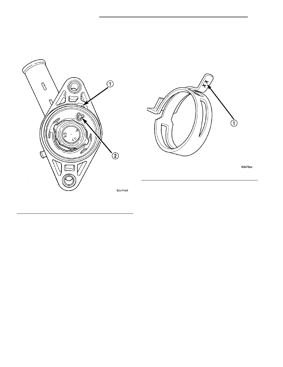
coolant outlet connector, aligning air bleed with the
location notch on outlet connector (Fig. 25).
(2) Install coolant outlet connector with thermostat
in position onto thermostat housing (Fig. 23). Tighten
bolts to 12.5 N·m (110 in. lbs.).
(3) Turbocharger equipped vehicles:
• Attach A/C suction line support bracket to A/C
suction line.
• Install fastener securing A/C suction line sup-
port bracket to coolant oulet connector.
(4) Connect upper radiator hose.
(5) Connect the coolant recovery system hose.
(6) Install upper intake manifold (Refer to 9 -
ENGINE/MANIFOLDS/INTAKE
MANIFOLD
-
INSTALLATION).
(7) Fill cooling system (Refer to 7 - COOLING/EN-
GINE - STANDARD PROCEDURE).
HOSE CLAMPS
DESCRIPTION - HOSE CLAMPS
The cooling system utilizes both worm drive and
spring type hose clamps. If a spring type clamp
replacement is necessary, replace with the original
Mopar
t equipment spring type clamp.
CAUTION: A number or letter is stamped into the
tongue of constant tension clamps. If replacement
is necessary, use only a original equipment clamp
with matching number or letter (Fig. 26).
OPERATION
The worm type hose clamp uses a specified torque
value to maintain proper tension on a hose connection.
The spring type hose clamp applies constant ten-
sion on a hose connection. To remove a spring type
hose clamp, only use constant tension clamp pliers
(Special Tool 8495) designed to compress the hose
clamp. For Special Tool Identification, (Refer to 7 -
COOLING - SPECIAL TOOLS).
RADIATOR FAN
DESCRIPTION
Non-Turbo
The radiator cooling fan is a dual-speed electric motor
driven fan. The radiator fan assembly includes an elec-
tric motor, fan blade, and a support shroud that is
attached to the radiator (Fig. 31). The radiator fan is
serviced as an assembly (fan motor/fan/shroud).
Turbo
The radiator cooling fan is a variable speed electric
motor driven fan. The radiator fan assembly includes
an electric motor, fan blade, and a support shroud
that is attached to the radiator (Fig. 32). The radia-
tor fan is serviced as an assembly (fan motor/fan/
shroud).
Fig. 25 Thermostat Position
1 - LOCATOR NOTCH
2 - AIR BLEED
Fig. 26 Spring Clamp Size Location
1 - SPRING CLAMP SIZE LOCATION
7 - 54
ENGINE - 2.0/2.4L DOHC
PT
ENGINE COOLANT THERMOSTAT (Continued)