Chrysler Stratus Convertible. Manual - part 239
(5) Pull instrument panel top cover up enough to
gain access to knee bolster screws (Fig. 18).
(6) Remove lower knee bolster screws and knee
bolster.
(7) Remove screws from lower steering column
shroud (Fig. 19).
(8) Pull lower shroud to clear ignition cylinder and
key release, if equipped (Fig. 20).
(9) Hold tilt wheel lever down and slide lower
shroud forward to remove it from column (Fig. 21).
(10) Tilt wheel to full down position and remove
upper steering column shroud.
(11) Remove screws holding multi-function switch
to lock housing (Fig. 22).
(12) Place key cylinder in RUN position. Depress
lock cylinder retaining tab and remove key cylinder
(Fig. 23).
(13) Disconnect electrical connectors from ignition
switch (Fig. 24) and (Fig. 25).
(14) Remove ignition switch mounting screw (Fig.
24) with a #10 Torx
t tamper proof bit.
(15) Depress retaining tabs (Fig. 14) and pull igni-
tion switch from steering column.
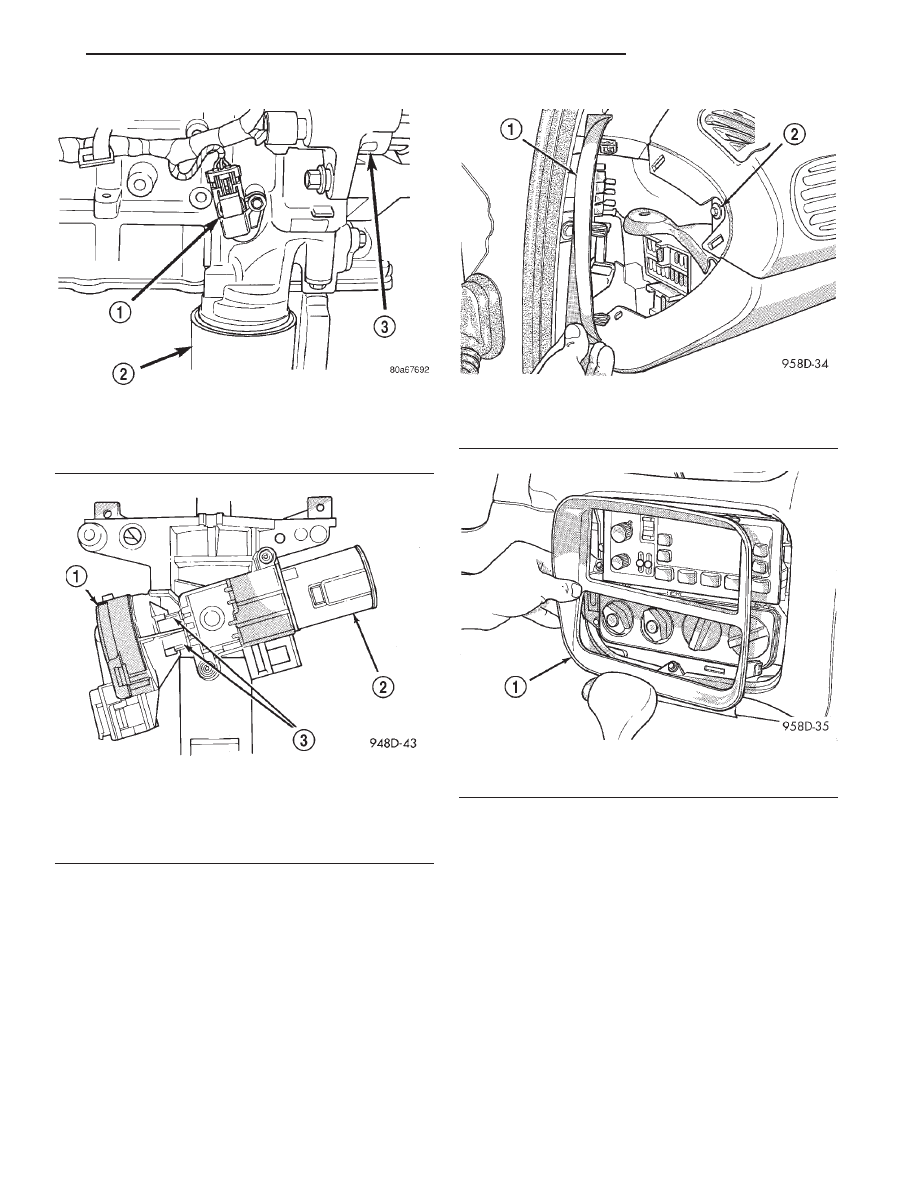
Fig. 13 Crankshaft Position Sensor—2.0L
1 – CRANKSHAFT POSITION SENSOR
2 – OIL FILTER
3 – GENERATOR
Fig. 14 Ignition Switch—Viewed From Below
Column
1 – IGNITION SWITCH
2 – LOCK CYLINDER HOUSING
3 – RETAINING TABS
Fig. 15 Instrument Panel Top Cover—Left End
1 – FUSE PANEL COVER
2 – TOP COVER SCREW
Fig. 16 Center Bezel
1 – CENTER BEZEL
JX
IGNITION SYSTEM
8D - 7
REMOVAL AND INSTALLATION (Continued)