Chrysler Stratus Convertible. Manual - part 238
sensor signals when the ignition switch is in the Run
position, it will de-energize the ASD relay.
ELECTRONIC IGNITION COIL
DESCRIPTION
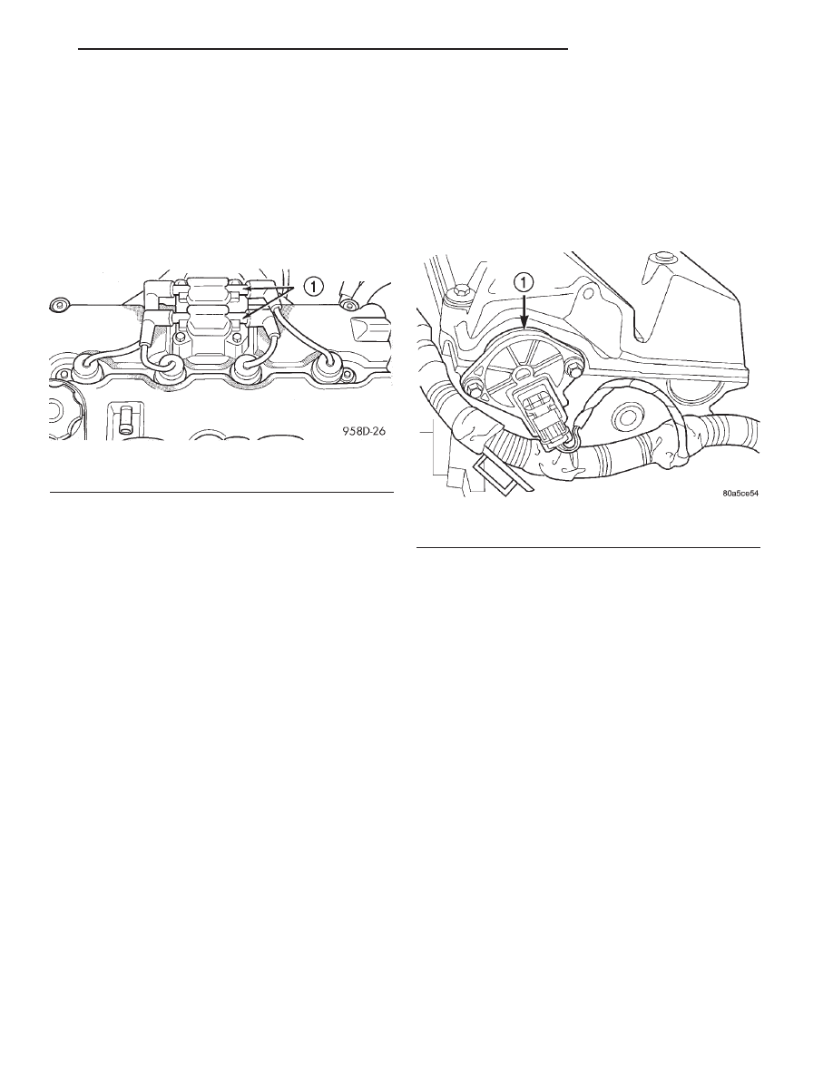
The coil pack consists of 2 coils molded together.
The coil pack is mounted on the valve cover (Fig. 3).
High tension leads route to each cylinder from the
coil.
OPERATION
WARNING: THE DIRECT IGNITION SYSTEM GEN-
ERATES
APPROXIMATELY
40,000
VOLTS.
PER-
SONAL INJURY COULD RESULT FROM CONTACT
WITH THIS SYSTEM.
The coil fires two spark plugs every power stroke.
One plug is the cylinder under compression, the
other cylinder fires on the exhaust stroke. Coil num-
ber one fires cylinders 1 and 4. Coil number two fires
cylinders 2 and 3. The PCM determines which of the
coils to charge and fire at the correct time.
The Auto Shutdown (ASD) relay provides battery
voltage to the ignition coil. The PCM provides a
ground contact (circuit) for energizing the coil. When
the PCM breaks the contact, the energy in the coil
primary transfers to the secondary causing the
spark. The PCM will de-energize the ASD relay if it
does not receive the crankshaft position sensor and
camshaft position sensor inputs. Refer to Auto Shut-
down (ASD) Relay—PCM Output, in this section for
relay operation.
CAMSHAFT POSITION SENSOR—2.0L
DESCRIPTION
The camshaft position sensor attaches to the rear
of the cylinder head (Fig. 5). A target magnet
attaches to the rear of the camshaft and indexes to
the correct position. The sensor also acts as a thrust
plate to control camshaft endplay.
OPERATION
The PCM determines fuel injection synchronization
and cylinder identification from inputs provided by
the camshaft position sensor (Fig. 4) and crankshaft
position sensor. From the two inputs, the PCM deter-
mines crankshaft position.
The
target
magnet
has
four
different
poles
arranged in an asymmetrical pattern. As the target
magnet rotates, the camshaft position sensor senses
the change in polarity (Fig. 6). The sensor input
switches from high (5 volts) to low (0.30 volts) as the
target magnet rotates. When the north pole of the
target magnet passes under the sensor, the output
switches high. The sensor output switches low when
the south pole of the target magnet passes under-
neath.
KNOCK SENSOR
DESCRIPTION
The knock sensor threads into the cylinder block.
OPERATION
When the knock sensor detects a knock in one of
the cylinders, it sends an input signal to the PCM. In
response, the PCM retards ignition timing for all cyl-
inders by a scheduled amount.
Knock sensors contain a piezoelectric material
which constantly vibrates and sends an input voltage
(signal) to the PCM while the engine operates. As the
intensity of the crystal’s vibration increases, the
knock sensor output voltage also increases.
Fig. 3 Ignition Coil Pack—2.0L Engine
1 – IGNITION COILS
Fig. 4 Camshaft Position Sensor—2.0L DOHC
1 – CAMSHAFT POSITION SENSOR
JX
IGNITION SYSTEM
8D - 3
DESCRIPTION AND OPERATION (Continued)