Chrysler Stratus Convertible. Manual - part 237
 

  Index      Chrysler     Chrysler Stratus Convertible - service repair manual 1995-2000 year


Search            


Content   ..  235  236  237  238   ..


Chrysler Stratus Convertible. Manual - part 237


(4) Turn the key to the Off position. Remove the

key.

(5) Install steering column shrouds.
(6) Connect negative cable to auxillary battery ter-

minal on shock tower.

IGNITION INTERLOCK

Refer to the Transaxle section for Shifter/Ignition

Interlock Service.

LOCK CYLINDER HOUSING

Refer to Steering Column in Group 19, Steering,

for Lock Cylinder Housing Service.

SPECIFICATIONS

VEHICLE EMISSION CONTROL INFORMATION
LABEL

DESCRIPTION

All models have a Vehicle Emission Control Infor-

mation (VECI) Label. Chrysler permanently attaches
the label in the engine compartment. It cannot be
removed without defacing information and destroying
the label.

The label contains the vehicle’s emission specifica-

tions and vacuum hose routings. All hoses must be
connected and routed according to the label.

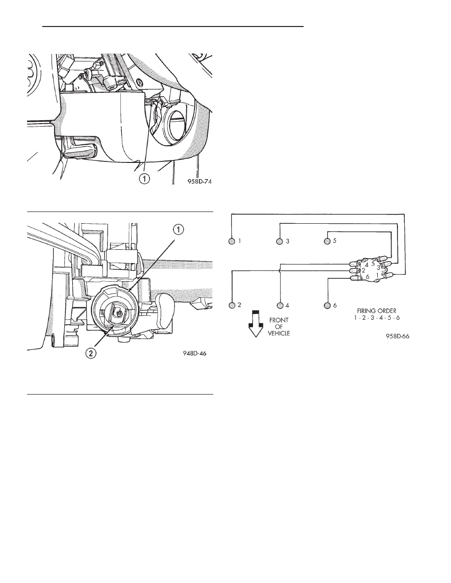
FIRING ORDER

TORQUE SPECIFICATION

DESCRIPTION

TORQUE

Air Inlet tube Clamp . . . . . . . . . 3 N·m (25 in. lbs.)
Camshaft Position Sensor Screw . . . . . . . . . 12 N·m

(105 in. lbs.)

Coolant Sensor—2.5L . . . . . . . . 27 N·m (20 ft. lbs.)
Crankshaft Position Sensor Screw . . . . . . . 12 N·m

(105 in. lbs.)

Coolant Temp. Sensor . . . . . 18.6 N·m (165 in. lbs.)
Distributor Holddown Nut—2.5L . . . . . . . . 13 N·m

(9 ft. lbs.)

EGR Tube to Intake . . . . . . . . . 11 N·m (95 in. lbs.)
IAT Sensor—2.5L . . . . . . . . . 11.5 N·m (100 in. lbs.)
Knock Sensor . . . . . . . . . . . . . . 10 N·m (90 in. lbs.)
MAP Sensor—2.5L . . . . . . . . . 3.4 N·m (30 in. lbs.)
Spark Plugs . . . . . . . . . . . . . . . . 28 N·m (20 ft. lbs.)

Fig. 29 Lock Cylinder Retaining Tab

1 – LOCK CYLINDER RETAINING TAB

Fig. 30 Socket in Lock Cylinder Housing

1 – LOCK CYLINDER HOUSING
2 – SOCKET

FIRING ORDER—2.5L

JX

IGNITION SYSTEM

8D - 13

REMOVAL AND INSTALLATION (Continued)

SPARK PLUG CABLE RESISTANCE—2.5L

SPARK PLUGS

Engine

Spark Plug

Gap

Thread Size

2.4L

RC12YC5

0.048 TO 0.053

14mm (3/4 in.) reach

2.5L

RC10PYP4

0.038 TO 0.043

14mm (3/4 in.) reach

IGNITION COIL

Engines

Coil Manufacture

Primary Resistance at
21°C-27°C (70°F-80°F)

Secondary Resistance at 21°C-27°C
(70°F-80°F)

2.5L

Melco

0.6 TO 0.8 Ohms

12,500 to 18,000 Ohms

MINIMUM

MAXIMUM

250 Ohms Per Inch

560 Ohms Per Inch

3000 Ohms Per Foot

6700 Ohms Per Foot

8D - 14

IGNITION SYSTEM

JX

SPECIFICATIONS (Continued)

IGNITION SYSTEM

TABLE OF CONTENTS

page

page

DESCRIPTION AND OPERATION

IGNITION SYSTEM . . . . . . . . . . . . . . . . . . . . . . . . 1
SPARK PLUGS RESISTER . . . . . . . . . . . . . . . . . . 1
SPARK PLUG CABLES . . . . . . . . . . . . . . . . . . . . . 1
ELECTRONIC IGNITION COIL . . . . . . . . . . . . . . . . 2
AUTOMATIC SHUTDOWN RELAY. . . . . . . . . . . . . 2
ELECTRONIC IGNITION COIL . . . . . . . . . . . . . . . . 3
CAMSHAFT POSITION SENSOR—2.0L . . . . . . . . 3
KNOCK SENSOR. . . . . . . . . . . . . . . . . . . . . . . . . . 3
LOCK KEY CYLINDER. . . . . . . . . . . . . . . . . . . . . . 4
IGNITION INTERLOCK . . . . . . . . . . . . . . . . . . . . . 4

REMOVAL AND INSTALLATION

SPARK PLUG CABLES – 2.0L . . . . . . . . . . . . . . . 4
SPARK PLUGS – 2.0L . . . . . . . . . . . . . . . . . . . . . 5
IGNITION COIL – 2.0L . . . . . . . . . . . . . . . . . . . . . 5

AUTOMATIC SHUTDOWN RELAY. . . . . . . . . . . . . 5
CAMSHAFT POSITION SENSOR—DOHC . . . . . . . 5
CRANKSHAFT POSITION SENSOR – 2.0 L . . . . . 6
IGNITION SWITCH . . . . . . . . . . . . . . . . . . . . . . . . 6
LOCK KEY CYLINDER. . . . . . . . . . . . . . . . . . . . . . 9
IGNITION INTERLOCK . . . . . . . . . . . . . . . . . . . . 10
LOCK CYLINDER HOUSING . . . . . . . . . . . . . . . . 10

SPECIFICATIONS

VEHICLE EMISSION CONTROL

INFORMATION LABEL . . . . . . . . . . . . . . . . . . . 10

FIRING ORDER . . . . . . . . . . . . . . . . . . . . . . . . . . 11
TORQUE SPECIFICATION . . . . . . . . . . . . . . . . . . 11
SPARK PLUG CABLE RESISTANCE—2.0L. . . . . 11
SPARK PLUGS . . . . . . . . . . . . . . . . . . . . . . . . . . 11
IGNITION COILS . . . . . . . . . . . . . . . . . . . . . . . . . 11

DESCRIPTION AND OPERATION

IGNITION SYSTEM

DESCRIPTION

NOTE: The 2.0L engine use a fixed ignition timing
system. Basic ignition timing is not adjustable. All
spark advance is determined by the Powertrain
Control Module (PCM).

The distributorless ignition system used on 2.0L

engine is referred to as the Direct Ignition System
(DIS). Basic ignition timing is not adjustable.
The system’s three main components are the coil
pack, crankshaft position sensor, and camshaft posi-
tion sensor.

OPERATION

The crankshaft position sensor and camshaft posi-

tion sensor are hall effect devices. The camshaft posi-
tion sensor and crankshaft position sensor generate
pulses that are inputs to the PCM. The PCM deter-
mines crankshaft position from these sensors. The
PCM calculates injector sequence and ignition timing
from crankshaft position. For a description of both
sensors, refer to Camshaft Position Sensor and
Crankshaft Position Sensor in this section.

SPARK PLUGS RESISTER

DESCRIPTION

All engines use resistor spark plugs. They have

resistance values ranging from 6,000 to 20,000 ohms
when checked with at least a 1000 volt spark plug
tester.

Do not use an ohm meter to check the resis-

tance of the spark plugs. This will give an inac-
curate reading.

Refer to the Specifications section for gap and type

of spark plug.

SPARK PLUG CABLES

DESCRIPTION

Spark Plug cables are sometimes referred to as

secondary ignition wires. They transfer electrical cur-
rent from the coil pack (2.0L), to individual spark
plugs at each cylinder. The resistor type, nonmetallic
spark plug cables provide suppression of radio fre-
quency emissions from the ignition system.

Check the spark plug cable connections for good

contact at the coil and distributor cap towers and at
the spark plugs. Terminals should be fully seated.
The nipples and spark plug covers should be in good
condition. Nipples should fit tightly on the coil and
distributor cap towers and spark plug cover should
fit tight around spark plug insulators. Loose cable
connections can cause ignition malfunctions by per-

JX

IGNITION SYSTEM

8D - 1

mitting water to enter the towers, corroding, and
increasing resistance. To maintain proper sealing
at the terminal connections, the connections
should not be broken unless testing indicates
high resistance, an open circuit or other dam-
age.

Clean high tension cables with a cloth moistened

with a non-flammable solvent and wipe dry. Check
for brittle or cracked insulation. Plastic clips in vari-
ous locations protect the cables from damage. When
the cables are replaced the clips must be used to pre-
vent damage to the cables.

ELECTRONIC IGNITION COIL

DESCRIPTION

The coil pack consists of 2 coils molded together.

The coil pack is mounted on the valve cover (Fig. 1).
High tension leads route to each cylinder from the
coil.

OPERATION

WARNING: THE DIRECT IGNITION SYSTEM GEN-
ERATES

APPROXIMATELY

40,000

VOLTS.

PER-

SONAL INJURY COULD RESULT FROM CONTACT
WITH THIS SYSTEM.

The coil fires two spark plugs every power stroke.

One plug is the cylinder under compression, the
other cylinder fires on the exhaust stroke. Coil num-
ber one fires cylinders 1 and 4. Coil number two fires
cylinders 2 and 3. The PCM determines which of the
coils to charge and fire at the correct time.

The Auto Shutdown (ASD) relay provides battery

voltage to the ignition coil. The PCM provides a
ground contact (circuit) for energizing the coil. When
the PCM breaks the contact, the energy in the coil
primary transfers to the secondary causing the
spark. The PCM will de-energize the ASD relay if it
does not receive the crankshaft position sensor and
camshaft position sensor inputs. Refer to Auto Shut-

down (ASD) Relay—PCM Output, in this section for
relay operation.

AUTOMATIC SHUTDOWN RELAY

DESCRIPTION

The ASD relay is located in the PDC (Fig. 2). The

inside top of the PDC cover has a label showing relay
and fuse identification.

OPERATION

The Automatic Shutdown (ASD) relay supplies bat-

tery voltage to the fuel injectors, generator field, elec-
tronic ignition coil and the heating elements in the
oxygen sensors.

Refer to the Wiring Diagrams for circuit informa-

tion.

The PCM controls the ASD relay by switching the

ground path for the solenoid side of the relay on and
off. The PCM turns the ground path off when the
ignition switch is in the Off position unless the O2
Heater Monitor test is being run. Refer to the
On-Board Diagnostics in the Emission Control sec-
tion. When the ignition switch is in On or Start, the
PCM momentarily turns on the ASD relay. While the
relay is on the PCM monitors the crankshaft and
camshaft position sensor signals to determine engine
speed and ignition timing (coil dwell). If the PCM
does not receive crankshaft and camshaft position

Fig. 1 Ignition Coil Pack—2.4L Engine

1 – IGNITION COILS

Fig. 2 Power Distribution Center (PDC)

1 – POWER DISTRIBUTION CENTER
2 – POWERTRAIN CONTROL MODULE

8D - 2

IGNITION SYSTEM

JX

DESCRIPTION AND OPERATION (Continued)


Content   ..  235  236  237  238   ..