Chrysler Stratus Convertible. Manual - part 207


  Index      Chrysler     Chrysler Stratus Convertible - service repair manual 1995-2000 year


Search            


Content   ..  205  206  207  208   ..


Chrysler Stratus Convertible. Manual - part 207


PROPORTIONING VALVE

NOTE: The following procedure is for the diagnosis
and testing of the proportioning valve(s) on a vehi-
cle equipped with ABS. For diagnosis and testing of
proportioning valves on a vehicle without ABS,
Refer to the BASE BRAKE SYSTEM section in this
group.

If a condition of premature rear wheel skid occurs

on a vehicle, the proportioning valve should always
be tested prior to it being replaced. This is due to the
fact that there are conditions other then a faulty pro-
portioning valve which can cause a premature rear
wheel skid.

One proportioning valve controls the right rear

brake, and the other proportioning valve controls the
left rear brake (Fig. 17). Therefore, a road test to
determine which rear brake slides first is essential.
Once the wheel which is skidding first is determined,
use the following procedure to diagnose the propor-
tioning valve.

The test procedure is the same for both rear wheel

proportioning valves. After road testing vehicle to
determine which wheel skids first, follow the proce-
dure below for testing the required proportioning
valve.

(1) Remove the cover (Fig. 18) securing the chassis

brake tubes and the fuel lines to the vehicle floor
pan.

(2) Remove the chassis brake tubes (Fig. 17) from

the proportioning valve controlling the rear wheel of
the vehicle which has premature wheel skid.

(3) Remove the proportioning valve from the rear

brake chassis tube.

(4) Remove the routing clips for the chassis brake

tubes and fuel lines from the floor pan.

CAUTION: The

chassis

brake

tube

must

be

removed from the routing clips. This is to prevent
the chassis brake tube from having to be bent when
installing the proportioning valve with the pressure
test fittings.

(5) Remove the chassis brake tube that requires

testing of its proportioning valve from the routing
clips.

CAUTION: Be sure the pressure test fittings being
installed into the proportioning valve have the cor-
rect thread sizes and flares for installation into the
proportioning valve and for installation of the chas-
sis brake tubes.

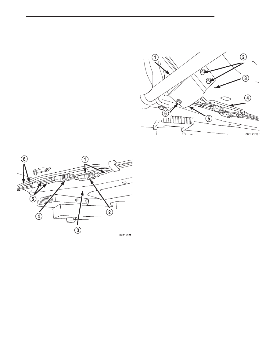
Fig. 17 Proportioning Valve Location

1 – CHASSIS BRAKE TUBES
2 – RIGHT REAR BRAKE PROPORTIONING VALVE
3 – RIGHT FRAME RAIL
4 – LEFT REAR BRAKE PROPORTIONING VALVE
5 – CHASSIS BRAKE TUBES
6 – FUEL TUBES

Fig. 18 Tube Bundle Cover

1 – STABILIZER BAR
2 – MOUNTING BOLTS
3 – FLOOR PAN
4 – TUBE BUNDLE
5 – COVER
6 – MOUNTING BOLT

JX

BRAKES

5 - 91

DIAGNOSIS AND TESTING (Continued)

(6) Install Pressure Test Fitting, Special Tool

6833-1 in the inlet port of the proportioning valve
(Fig. 19). Install Pressure Test Fitting, Special Tool
8187–2 in the outlet port of the proportioning valve
(Fig. 19). Tighten tube nuts to a torque of 17 N·m
(145 in. lbs.)

(7) Install the proportioning valve with the pres-

sure test fittings installed, in the chassis brake tube
(Fig. 20). Tighten both tube nuts to a torque of 17
N·m (145 in. lbs.).

(8) Install

a

Pressure

Gauge,

Special

Tool

C-4007-A into each pressure test fitting (Fig. 21).
Bleed air out of hose from pressure test fitting to
pressure gauge, at pressure gauge to remove all
trapped air.

(9) With the aid of a helper, apply pressure to the

brake pedal until reading on proportioning valve
inlet gauge, is at the pressure shown on the following
chart, PROPORTIONING VALVE APPLICATIONS
AND PRESSURE SPECIFICATIONS. Then check
the pressure reading on the proportioning valve out-
let gauge. If proportioning valve outlet pressure does
not agree with value shown on the following chart,
when inlet pressure shown on chart is obtained,
replace the proportioning valve. If proportioning
valve is within pressure specifications do not replace
proportioning valve.

(10) Check rear wheel brake shoe linings for con-

tamination or for replacement brake shoes not meet-
ing OEM brake lining material specifications. These
conditions can also be a possible cause for a prema-
ture rear wheel skid.

(11) Install proportioning valve on end of brake

flex hose. Tighten the proportioning valve to a torque
of 17 N·m (145 in. lbs.).

(12) Install brake tube on proportioning valve.

Torque tube nut to 17 N·m (145 in. lbs.) torque.

(13) Bleed the affected brake line. Refer to BASE

BRAKE

BLEEDING

in

the

SERVICE

PROCE-

DURES section.

Fig. 19 Pressure Test Fittings Installed On

Proportioning Valve

1 – SPECIAL TOOL 8187–2
2 – SPECIAL TOOL 6833–1
3 – PROPORTIONING VALVE

Fig. 20 Proportioning Valve With Pressure Test

Fittings Installed

1 – CHASSIS BRAKE TUBE FROM HCU
2 – PROPORTIONING VALVE
3 – CHASSIS BRAKE TUBE TO REAR BRAKE
4 – SPECIAL TOOL 8187–2
5 – SPECIAL TOOL 6833–1

Fig. 21 Pressure Gauges Installed On Pressure Test

Fittings

1 – PRESSURE TEST FITTING
2 – SPECIAL TOOL C-4007–A
3 – BLEED AIR FROM BOTH PRESSURE GAUGES HERE
4 – PRESSURE TEST FITTING

5 - 92

BRAKES

JX

DIAGNOSIS AND TESTING (Continued)

PROPORTIONING VALVE APPLICATIONS AND PRESSURE SPECIFICATIONS

Sales

Code

Brake System Type

Split Point

Slope

Identification

Inlet

Pressure

Outlet Pressure

BRA

14” Disc/Drum

600 psi

0.59

Bar Code

Label

1000 psi

800-900 psi

BRJ

14” Disc/Drum

W/ABS

600 psi

0.59

Bar Code

Label

1000 psi

800-900 psi

BRF

14” Disc/Disc W/ABS

500 psi

0.43

Bar Code

Label

1000 psi

600-700 psi

BRAKE FLUID CONTAMINATION

Indications of fluid contamination are swollen or

deteriorated rubber parts. Swelling indicates the
presence of petroleum in the brake fluid.

To test for contamination, put a small amount of

drained brake fluid in clear glass jar. If the fluid sep-
arates into layers, there is mineral oil or other fluid
contamination of the brake fluid.

If the brake fluid is contaminated, drain and thor-

oughly flush the brake system. Replace all the rubber
parts or components containing rubber coming into
contact with the brake fluid including: the master
cylinder; proportioning valves; caliper seals; wheel
cylinder seals; ABS hydraulic control unit; and all
hydraulic fluid hoses.

SERVICE PROCEDURES

BRAKE FLUID LEVEL CHECKING

CAUTION: Use only Mopar brake fluid or an equiv-
alent from a tightly sealed container. Brake fluid
must conform to DOT 3 specifications. Do not use
petroleum-based fluid because seal damage in the
brake system will result.

Refer to SERVICE PROCEDURES in the BASE

BRAKE SYSTEM section in this group for the proper
procedure to check and adjust the brake fluid level in
the master cylinder fluid reservoir.

ANTILOCK BRAKE SYSTEM BLEEDING

The base brake’s hydraulic system must be bled

anytime air enters the hydraulic system. The ABS
though, particularly the ICU (HCU), should only be
bled when the HCU is replaced or removed from the
vehicle. The ABS must always be bled anytime it is
suspected that the HCU has ingested air. Under
most circumstances that require the bleeding of the
brakes

hydraulic

system,

only

the

base

brake

hydraulic system needs to be bled.

It is important to note that excessive air in the

brake system will cause a soft or spongy feeling
brake pedal.

During the brake bleeding procedure, be sure the

brake fluid level remains close to the FULL level in
the master cylinder fluid reservoir. Check the fluid
level periodically during the bleeding procedure and
add DOT 3 brake fluid as required.

The ABS must be bled as two independent braking

systems. The non-ABS portion of the brake system
with ABS is to be bled the same as any non-ABS sys-
tem.

The ABS portion of the brake system must be bled

separately. Use the following procedure to properly
bleed the brake hydraulic system including the ABS.

BLEEDING

When bleeding the ABS system, the following

bleeding sequence must be followed to insure com-
plete and adequate bleeding.

(1) Make sure all hydraulic fluid lines are installed

and properly torqued.

(2) Connect the DRB scan tool to the diagnostics

connector. The diagnostic connector is located under
the lower steering column cover to the left of the
steering column.

(3) Using the DRB, check to make sure the CAB

does not have any fault codes stored. If it does, clear
them using the DRB.

WARNING: WHEN BLEEDING THE BRAKE SYSTEM
WEAR SAFETY GLASSES. A CLEAR BLEED TUBE
MUST BE ATTACHED TO THE BLEEDER SCREWS
AND SUBMERGED IN A CLEAR CONTAINER FILLED
PART WAY WITH CLEAN BRAKE FLUID. DIRECT
THE FLOW OF BRAKE FLUID AWAY FROM YOUR-
SELF AND THE PAINTED SURFACES OF THE VEHI-
CLE. BRAKE FLUID AT HIGH PRESSURE MAY
COME OUT OF THE BLEEDER SCREWS WHEN
OPENED.

JX

BRAKES

5 - 93

DIAGNOSIS AND TESTING (Continued)

(4) Bleed the base brake system using the stan-

dard pressure or manual bleeding procedure as out-
lined in SERVICE PROCEDURES in the BASE
BRAKE SYSTEM section at the beginning of this
group.

(5) Using the DRB, select ANTILOCK BRAKES,

followed

by

MISCELLANEOUS,

then

BLEED

BRAKES. Follow the instructions displayed. When
the scan tool displays TEST COMPLETED, discon-
nect the scan tool and proceed.

(6) Bleed the base brake system a second time.

Check brake fluid level in the reservoir periodically
to prevent emptying, causing air to enter the hydrau-
lic system.

(7) Fill the master cylinder reservoir to the full

level.

(8) Test drive the vehicle to be sure the brakes are

operating correctly and that the brake pedal does not
feel spongy.

REMOVAL AND INSTALLATION

SERVICE WARNINGS AND CAUTIONS

Review this entire section prior to performing any

mechanical work on a vehicle equipped with ABS.
This section contains information on precautions per-
taining to potential component damage, vehicle dam-
age and personal injury which could result when
servicing an ABS equipped vehicle.

CAUTION: Only the recommended jacking or hoist-
ing positions for this vehicle are to be used when-
ever it is necessary to lift a vehicle. Failure to raise
a vehicle from the recommended locations could
result in lifting a vehicle by the hydraulic control
unit mounting bracket. Lifting a vehicle by the
hydraulic control unit mounting bracket will result
in damage to the mounting bracket and the hydrau-
lic control unit.

CAUTION: An attempt to remove or disconnect cer-
tain system components may result in improper
system operation. Only those components with
approved removal and installation procedures in
this manual should be serviced.

CAUTION: Brake fluid will damage painted sur-
faces. If brake fluid is spilled on any painted sur-
faces, wash off with water immediately.

CAUTION: When performing any service procedure
on a vehicle equipped with ABS do not apply a
12-volt power source to the ground circuit of the
pump motor in the HCU. Doing this will damage the
pump motor and will require replacement of the
entire HCU.

CAUTION: If welding work is to be performed on
the vehicle, using an electric arc welder, the CAB
connector should be disconnected during the weld-
ing operation.

CAUTION: The CAB 25-way connector should never
be connected or disconnected with the ignition
switch in the ON position.

Many components of the ABS System are not ser-

viceable and must be replaced as an assembly. Do not
disassemble any component which is not designed to
be serviced.

INTEGRATED CONTROL UNIT

NOTE: Before proceeding, review SERVICE WARN-
INGS AND CAUTIONS at the beginning of this
REMOVAL AND INSTALLATION section.

REMOVAL

(1) Remove the remote ground cable from the

ground stud on the left strut tower (Fig. 22).

Fig. 22 Remote Ground Cable Attachment To Strut

Tower

1 – SPEED CONTROL SERVO
2 – LEFT STRUT TOWER
3 – GROUND STUD
4 – AIR CLEANER
5 – REMOTE GROUND CABLE
6 – MASTER CYLINDER

5 - 94

BRAKES

JX

SERVICE PROCEDURES (Continued)


Content   ..  205  206  207  208   ..