Chrysler Stratus Convertible. Manual - part 205
 

  Index      Chrysler     Chrysler Stratus Convertible - service repair manual 1995-2000 year


Search            


Content   ..  203  204  205  206   ..


Chrysler Stratus Convertible. Manual - part 205


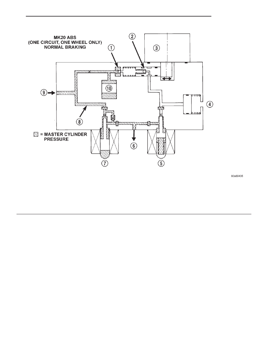
NORMAL BRAKING HYDRAULIC CIRCUIT AND
SOLENOID VALVE FUNCTION

The hydraulic diagram (Fig. 11) shows the vehicle

in the normal braking mode of the base brake
hydraulic system. The diagram shows no wheel spin
or slip occurring relative to the speed of the vehicle.
The driver is applying the brake pedal which builds
pressure in the brake hydraulic system to engage the
brakes and stop the vehicle.

Fig. 11 Normal Braking Hydraulic Circuit

1 – OUTLET VALVE
2 – PUMP PISTON
3 – PUMP MOTOR (OFF)
4 – LOW PRESSURE ACCUMULATOR
5 – NORMALLY CLOSED VALVE (OFF)

6 – TO RIGHT FRONT WHEEL
7 – NORMALLY OPEN VALVE (OFF)
8 – MASTER CYLINDER PRESSURE
9 – FROM MASTER CYLINDER
10 – NOISE DAMPER CHAMBER

JX

BRAKES

5 - 83

DESCRIPTION AND OPERATION (Continued)

ABS HYDRAULIC CIRCUIT AND SOLENOID VALVE
FUNCTION (ABS WITHOUT TRACTION CONTROL)

The hydraulic diagram (Fig. 12) shows the vehicle

in the ABS braking mode. The diagram shows one
wheel is slipping because the driver is attempting to
stop the vehicle at a faster rate than is allowed by
the surface on which the tires are riding.

• The normally open and normally closed valves

modulate (build/decay) the brake hydraulic pressure
as required.

• The pump/motor is switched on so that the

brake fluid from the low pressure accumulators is
returned to the master cylinder circuits.

• The brake fluid is routed to either the master

cylinder or the wheel brake depending on the posi-
tion of the normally open valve.

Fig. 12 ABS Without Traction Control - ABS Mode Hydraulic Circuit

1 – OUTLET VALVE
2 – PUMP PISTON
3 – PUMP MOTOR (ON)
4 – LOW PRESSURE ACCUMULATOR PRESSURE
5 – LOW PRESSURE ACCUMULATOR
6 – NORMALLY CLOSED VALVE (MODULATING)
7 – TO RIGHT FRONT WHEEL

8 – NORMALLY OPEN VALVE (MODULATING)
9 – FROM MASTER CYLINDER
10 – MASTER CYLINDER PRESSURE
11 – CONTROLLED WHEEL PRESSURE
12 – PUMP INTERSTAGE PRESSURE
13 – NOISE DAMPER CHAMBER

5 - 84

BRAKES

JX

DESCRIPTION AND OPERATION (Continued)

NORMAL BRAKING HYDRAULIC CIRCUIT,
SOLENOID VALVE, AND SHUTTLE VALVE
FUNCTION (ABS WITH TRACTION CONTROL)

The hydraulic diagram (Fig. 13) shows a vehicle

with traction control in the normal braking mode.
The diagram shows no wheel spin or slip occurring

relative to the speed of the vehicle. The driver is
applying the brake pedal which builds pressure in
the brake hydraulic system to engage the brakes and
stop the vehicle. the hydraulic shuttle valve closes
with every brake pedal application so pressure is not
created at the inlet to the pump/motor.

Fig. 13 ABS With Traction Control - Normal Braking Hydraulic Circuit

1 – OUTLET VALVE
2 – PUMP PISTON
3 – PUMP MOTOR (OFF)
4 – SUCTION VALVE
5 – LOW PRESSURE ACCUMULATOR
6 – NORMALLY CLOSED VALVE (OFF)
7 – TO RIGHT FRONT WHEEL

8 – NORMALLY OPEN VALVE (OFF)
9 – NORMALLY OPEN ASR VALVE (OFF)
10 – FROM MASTER CYLINDER
11 – HYDRAULIC SHUTTLE VALVE
12 – MASTER CYLINDER PRESSURE
13 – NOISE DAMPER CHAMBER

JX

BRAKES

5 - 85

DESCRIPTION AND OPERATION (Continued)

ABS BRAKING HYDRAULIC CIRCUIT, SOLENOID
VALVE, AND SHUTTLE VALVE FUNCTION (ABS
WITH TRACTION CONTROL)

The hydraulic diagram (Fig. 14) shows the vehicle

in the ABS braking mode. The diagram shows one
wheel is slipping because the driver is attempting to
stop the vehicle at a faster rate than is allowed by
the surface on which the tires are riding.

• The hydraulic shuttle valve closes upon brake

application so that the pump/motor cannot siphon
brake fluid from the master cylinder.

• The normally open and normally closed valves

modulate (build/decay) the brake hydraulic pressure
as required.

• The pump/motor is switched on so that the

brake fluid from the low pressure accumulators is
returned to the master cylinder circuits.

• The brake fluid is routed to either the master

cylinder or the wheel brake depending on the posi-
tion of the normally open valve.

Fig. 14 ABS With Traction Control - ABS Mode Hydraulic Circuit

1 – OUTLET VALVE
2 – PUMP PISTON
3 – PUMP MOTOR (ON)
4 – SUCTION VALVE
5 – LOW PRESSURE ACCUMULATOR
6 – NORMALLY CLOSED VALVE (MODULATING)
7 – TO RIGHT FRONT WHEEL
8 – NORMALLY OPEN VALVE (MODULATING)

9 – NORMALLY OPEN ASR VALVE (OFF)
10 – FROM MASTER CYLINDER
11 – HYDRAULIC SHUTTLE VALVE
12 – MASTER CYLINDER PRESSURE
13 – CONTROLLED WHEEL PRESSURE
14 – LOW PRESSURE ACCUMULATOR PRESSURE
15 – PUMP INTERSTAGE PRESSURE
16 – NOISE DAMPER CHAMBER

5 - 86

BRAKES

JX

DESCRIPTION AND OPERATION (Continued)


Content   ..  203  204  205  206   ..