Chrysler Stratus Convertible. Manual - part 198
 

  Index      Chrysler     Chrysler Stratus Convertible - service repair manual 1995-2000 year


Search            


Content   ..  196  197  198  199   ..


Chrysler Stratus Convertible. Manual - part 198


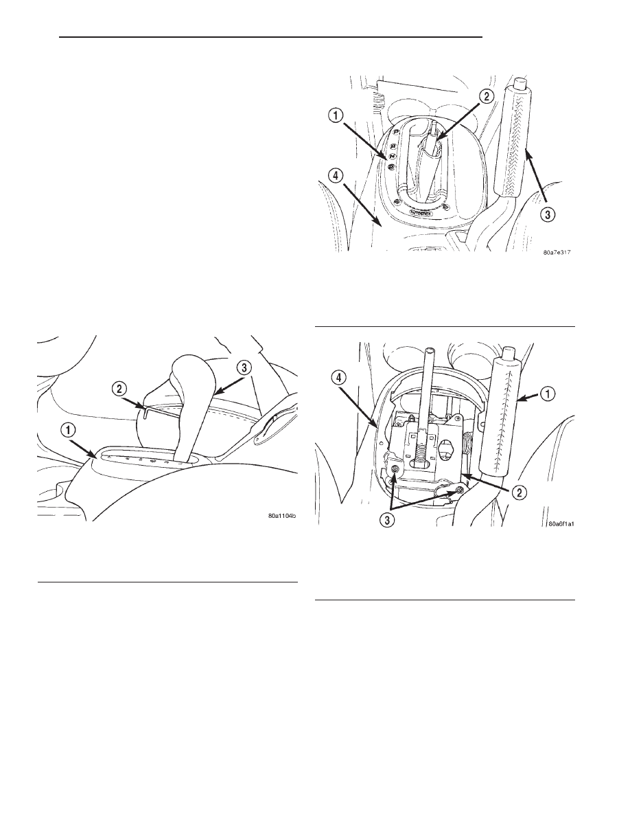
(14) Install the shift knob on the shifter. Install

and securely tighten the shift knob retaining screw
(Fig. 132).

PARKING BRAKE CABLE (REAR)

NOTE: Remove only one rear parking brake cable
from the vehicle at a time. Failure to do so will
result in high efforts required to connect the park-
ing brake cables to the tension equalizer and the
parking brake lever at the rear wheel brakes.

For servicing of either the left or right rear park-

ing brake cable, follow the procedure as listed below.

REMOVAL

(1) Remove the shift knob from the shifter. The

gear shift knob is attached to the shifter using
a set screw (Fig. 132). Access to the set screw is
from the front of the shift knob and is removed
using a 2 mm allen wrench.

(2) Remove the shift range indicator (Fig. 133)

from the center console. The shift range indicator is
attached to the center console using retaining clips.
It is removed by carefully prying it off the center con-
sole. The shift range indicator covers the 2 attaching
screws for the center console.

(3) Remove the 2 screws (Fig. 134) attaching the

center console to the shifter.

(4) Remove the 3 screws attaching the rear of the

center console to the console bracket (Fig. 135).

(5) Raise the park brake lever to a 45° angle. This

is required for clearance to remove the center con-
sole.

(6) Raise the rear of the center console high

enough to access the center console wiring harness
connector (Fig. 136). Disconnect the center console
wiring harness connector from the vehicle wiring
harness 10–way connector (Fig. 136).

(7) Remove the center console from the vehicle.
(8) Lower the park brake lever to its fully released

position.

Fig. 132 Shift Knob Retaining Screw

1 – CENTER CONSOLE
2 – ALLEN WRENCH
3 – SHIFT KNOB

Fig. 133 Shift Range Indicator

1 – SHIFT RANGE INDICATOR
2 – SHIFTER
3 – PARK BRAKE LEVER
4 – CENTER CONSOLE

Fig. 134 Center Console Front Attaching Screw

1 – PARK BRAKE HAND LEVER
2 – GEARSHIFT MECHANISM
3 – ATTACHING SCREWS
4 – CENTER CONSOLE

JX

BRAKES

5 - 55

REMOVAL AND INSTALLATION (Continued)

WARNING: THE AUTO ADJUSTING FEATURE OF
THIS PARK BRAKE LEVER CONTAINS A CLOCK
SPRING LOADED TO APPROXIMATELY 20 POUNDS.
DO NOT RELEASE THE PARK BRAKE CABLES
FROM

THE

EQUALIZER

UNTIL

THE

AUTO

ADJUSTER IS RELOADED. FAILURE TO RELOAD
THE ADJUSTER MECHANISM BEFORE REMOVING
PARK BRAKE CABLES FROM EQUALIZER COULD
RESULT IN SERIOUS INJURY.

(9) Reload the adjuster mechanism on the park

brake lever using the following procedure.

• Ensure the park brake lever is in the full down

position when attempting to pull on park brake
lever output cable (Fig. 137).

• Grasp the park brake lever output cable (Fig.

137) by hand and pull upward.

• Continue to pull upward on cable until a 15/64

drill bit can be inserted in the adjuster mechanism
as shown in (Fig. 137). This will lock-out the auto
adjuster mechanism removing the tension from the
park brake lever output cable. This will then allow
the rear park brake cables to be easily removed from
the equalizer.

NOTE: If the output cable of the park brake mech-
anism will not move when pulled on, first, be sure
the park brake lever is in the full down position. If
park brake lever is in the full down position and the
output cable will not move, use the following proce-
dure to reload the adjuster mechanism.

Using a screw driver (Fig. 138) push down on the

end of the clutch spring where shown (Fig. 138).
While end of clutch spring is held down, pull out-
ward on park brake mechanism output cable.

If output cable can not be pulled out of park

brake mechanism, by pulling directly on output
cable, use a screwdriver inserted in tension equal-
izer (Fig. 138) to assist in pulling on cable.

(10) Remove both rear wheel park brake cables

from the park brake cable tension equalizer (Fig.
139).

Fig. 135 Center Console Rear Attaching Screws

1 – CENTER CONSOLE COVER
2 – ATTACHING SCREWS
3 – CENTER CONSOLE

Fig. 136 Console Wiring Harness Connector

1 – DRIVER SEAT
2 – CENTER CONSOLE
3 – PASSENGER SEAT
4 – VEHICLE WIRING HARNESS
5 – 10–WAY CONNECTOR
6 – PARK BRAKE LEVER ASSEMBLY
7 – CENTER CONSOLE WIRING HARNESS

Fig. 137 Park Brake Lever Correctly Reloaded

1 – PARK BRAKE LEVER ASSEMBLY
2 – 15/64 DRILL BIT
3 – AUTOMATIC ADJUSTER MECHANISM
4 – PARK BRAKE HAND LEVER
5 – PARK BRAKE LEVER OUTPUT CABLE

5 - 56

BRAKES

JX

REMOVAL AND INSTALLATION (Continued)

NOTE: If auto adjuster was not reloaded before
removing the tension equalizer from both rear park
brake cables, (Fig. 139) the park brake lever output
cable (Fig. 139) will be pulled into the park brake
mechanism.

If this happens the auto adjuster can be reloaded

using the following procedure.

Using a screw driver (Fig. 138) push down on the

end of the clutch spring where shown (Fig. 138).

While end of clutch spring is held down, pull out-
ward on park brake mechanism output cable. If out-
put cable can not be pulled out of park brake
mechanism, by pulling directly on output cable, use
a screwdriver inserted in tension equalizer (Fig.
138) to assist in pulling on cable.

(11) Remove the rear seat lower cushion from the

vehicle.

(12) Remove scuff plates from right and left door

sills. Scuff plates are attached to door sills using
clips on bottom of scuff plates. Remove by carefully
prying scuff plate retaining clips out of door sills.

(13) Remove the quarter trim panel from both

sides of the vehicle. Refer to Group 23 Body in this
group of the service manual for the required removal
procedure.

(14) Remove the 2 wiring harness routing clips

from the cross car beam.

(15) Remove the 2 clips attaching the carpeting to

the cross car beam.

(16) Fold rear carpeting forward to expose park

brake cables.

(17) Remove the routing clip (Fig. 140) attaching

the rear park brake cables to the floor pan.

(18) Install the box end of a 1/2 in. wrench over

the park brake cable retainer as indicated in (Fig.
141). This will compress tabs on park brake cable
retainer, allowing cable to be removed from console
bracket. From under carpet, grasp park brake cable
housing and pull cable straight out of console
bracket.

(19) Raise vehicle on jackstands or centered on a

frame contact type hoist. See Hoisting in the Lubri-

Fig. 138 Releasing Clutch Spring

1 – SCREWDRIVER
2 – CLUTCH SPRING END
3 – CLUTCH SPRING
4 – PARK BRAKE HAND LEVER
5 – PARK BRAKE LEVER MECHANISM
6 – USING SCREWDRIVER PUSH DOWNWARD ON END OF

CLUTCH SPRING HERE.

7 – PARK BRAKE LEVER OUTPUT CABLE

Fig. 139 Park Brake Cables At Tension Equalizer

1 – REAR WHEEL PARK BRAKE CABLES
2 – PARK BRAKE LEVER OUTPUT CABLE
3 – PARK BRAKE LEVER ASSEMBLY
4 – PARK BRAKE CABLE TENSION EQUALIZER

Fig. 140 Park Brake Cable Attachment To Floor Pan

1 – FLOOR PAN
2 – ROUTING CLIP
3 – REAR PARK BRAKE CABLES
4 – VEHICLE CARPETING

JX

BRAKES

5 - 57

REMOVAL AND INSTALLATION (Continued)

cation and Maintenance section of this manual for
the required lifting procedure to be used for this
vehicle.

(20) Remove rear wheel and tire assembly from

the side of the vehicle requiring park brake cable ser-
vice.

(21) Remove the rear brake drum (Fig. 142) from

the rear hub/bearing assembly.

(22) Remove the dust cap (Fig. 143) from the rear

hub/bearing assembly.

(23) Remove the rear hub/bearing retaining nut

(Fig. 144).

(24) Remove the hub/bearing from the spindle.
(25) Remove the park brake cable from the park

brake actuating lever on the trailing brake shoe (Fig.
145).

(26) Remove park brake cable (Fig. 146) from rear

brake support plate. Park brake cable is removed
from brake support plate using a 1/2 in. wrench as
shown in (Fig. 146) to compress locking tabs on park
brake cable retainer.

(27) Raise vehicle.

Fig. 141 Compressing Park Brake Cable Retaining

Tabs

1 – CONSOLE BRACKET
2 – PARK BRAKE CABLE TENSION EQUALIZER
3 – PARK BRAKE LEVER OUTPUT CABLE
4 – REAR PARK BRAKE CABLES
5 – 1/2

88

BOX END WRENCH

Fig. 142 Rear Brake Drum

1 – REAR BRAKE DRUM
2 – REAR BRAKE SUPPORT PLATE
3 – SHOCK ASSEMBLY
4 – REAR LATERAL ARM
5 – HUB/BEARING ASSEMBLY

Fig. 143 Rear Hub/Bearing Dust Cap

1 – HUB/BEARING ASSEMBLY
2 – DUST CAP

Fig. 144 Hub/Bearing Retaining Nut

1 – RETAINING NUT
2 – SPINDLE
3 – HUB/BEARING ASSEMBLY

5 - 58

BRAKES

JX

REMOVAL AND INSTALLATION (Continued)


Content   ..  196  197  198  199   ..