Chrysler Stratus Convertible. Manual - part 197


  Index      Chrysler     Chrysler Stratus Convertible - service repair manual 1995-2000 year


Search            


Content   ..  195  196  197  198   ..


Chrysler Stratus Convertible. Manual - part 197


(5) Install rear hub and bearing assembly on rear

knuckle. Install a NEW hub and bearing assembly
retaining nut (Fig. 119). Tighten the hub and bearing
assembly retaining nut to a torque of 250 N·m (185
ft. lbs.). Install dust cap.

(6) Adjust brake shoes assemblies so as not to

interfere with brake drum installation.

(7) Install brake drum on rear hub/bearing assem-

bly.

(8) Bleed the vehicle’s base brakes hydraulic sys-

tem.

(9) After brake drums are installed, pump brake

pedal several times to do final adjustment of the
brake shoe assemblies.

(10) Install the wheel and tire assembly. Tighten

the wheel mounting stud nuts in proper sequence
until all nuts are torqued to half specification. Then
repeat the tightening sequence to the full specified
torque of 129 N·m (95 ft. lbs.).

PARKING BRAKE LEVER

REMOVAL

(1) Remove the shift knob from the shifter. The

shift knob is attached to the shifter using a set
screw (Fig. 122). Access to the set screw is from
the front of the shift knob and is removed using
a 2 mm allen wrench.

(2) Remove the 3 screws (Fig. 123) attaching the

rear of the center console to the console bracket.

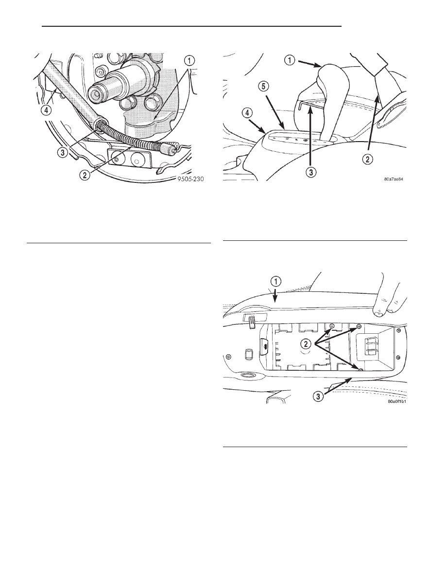
Fig. 121 Removing Park Brake Cable From Support

Plate

1 – REAR BRAKE SUPPORT PLATE
2 – PARK BRAKE CABLE
3 – PARK BRAKE CABLE RETAINER
4 – 1/2” BOX END WRENCH

Fig. 122 Shift Knob Retaining Screw

1 – SHIFT KNOB
2 – PARK BRAKE LEVER
3 – ALLEN WRENCH
4 – CENTER CONSOLE
5 – TRANSMISSION RANGE INDICATOR

Fig. 123 Center Console Rear Attaching Screws

1 – CENTER CONSOLE COVER
2 – ATTACHING SCREWS
3 – CENTER CONSOLE

JX

BRAKES

5 - 51

REMOVAL AND INSTALLATION (Continued)

(3) Remove the shift range indicator from the cen-

ter console. The shift range indicator is attached to
the center console using retaining clips. It is removed
by carefully prying it off the center console. The shift
range indicator covers the 2 screws attaching the
center console to the shifter mechanism. (Fig. 124).

(4) Remove the 2 screws (Fig. 125) attaching the

center console to the shifter.

(5) Raise the park brake hand lever to approxi-

mately a 45° angle. This is for the required clearance
to remove the center console.

(6) Raise the rear of the center console high

enough to access the center console wiring harness
connector (Fig. 126). Disconnect the center console
wiring harness connector from the vehicle wiring
harness 10 way connector (Fig. 126).

(7) Remove the center console from the vehicle.
(8) Lower park brake lever handle.

WARNING: THE AUTO ADJUSTING FEATURE OF
THIS PARK BRAKE LEVER CONTAINS A CLOCK
SPRING LOADED TO APPROXIMATELY 20 POUNDS.
DO NOT RELEASE THE PARK BRAKE CABLES
FROM

THE

EQUALIZER

UNTIL

THE

AUTO

ADJUSTER IS RELOADED. FAILURE TO RELOAD
THE ADJUSTER MECHANISM BEFORE REMOVING
PARK BRAKE CABLES FROM EQUALIZER COULD
RESULT IN SERIOUS INJURY.

(9) Reload the adjuster mechanism on the park

brake lever using the following procedure.

• Ensure the park brake lever is in the full down

position when attempting to pull on park brake
lever output cable (Fig. 127).

• Grasp the park brake lever output cable (Fig.

127) by hand and pull upward.

• Continue to pull upward on cable until a 15/64

drill bit can be inserted in the adjuster mechanism
as shown in (Fig. 127). This will lock-out the auto
adjuster mechanism removing the tension from the
park brake lever output cable. This will then allow
the rear park brake cables to be easily removed from
the equalizer.

Fig. 124 Shift Range Indicator

1 – SHIFT RANGE INDICATOR
2 – SHIFTER
3 – PARK BRAKE LEVER
4 – CENTER CONSOLE

Fig. 125 Center Console Front Attaching Screw

1 – PARK BRAKE HAND LEVER
2 – GEARSHIFT MECHANISM
3 – ATTACHING SCREWS
4 – CENTER CONSOLE

Fig. 126 Console Wiring Harness Connector

1 – DRIVER SEAT
2 – CENTER CONSOLE
3 – PASSENGER SEAT
4 – VEHICLE WIRING HARNESS
5 – 10–WAY CONNECTOR
6 – PARK BRAKE LEVER ASSEMBLY
7 – CENTER CONSOLE WIRING HARNESS

5 - 52

BRAKES

JX

REMOVAL AND INSTALLATION (Continued)

NOTE: If the output cable of the park brake mech-
anism will not move when pulled on, first, be sure
the park brake lever is in the full down position. If
park brake lever is in the full down position and the
output cable will not move, use the following proce-
dure to reload the adjuster mechanism.

Using a screw driver (Fig. 128) push down on the

end of the clutch spring where shown (Fig. 128).
While end of clutch spring is held down, pull out-
ward on park brake mechanism output cable.

If output cable can not be pulled out of park

brake mechanism, by pulling directly on output
cable, use a screwdriver inserted in tension equal-
izer (Fig. 128) to assist in pulling on cable.

(10) Remove the rear wheel park brake cables

from the park brake cable tension equalizer (Fig.
129).

NOTE: If auto adjuster was not reloaded before
removing the tension equalizer from both rear park
brake cables, (Fig. 128) the park brake lever output
cable (Fig. 128) will be pulled into the park brake
mechanism.

If this happens the auto adjuster can be reloaded

using the following procedure.

Using a screw driver (Fig. 128) push down on the

end of the clutch spring where shown (Fig. 128).
While the end of the clutch spring is held down,
pull outward on park brake mechanism output
cable. If output cable can not be pulled out of park
brake mechanism, by pulling directly on output
cable, use a screwdriver inserted in tension equal-
izer (Fig. 128) to assist in pulling on cable.

(11) Disconnect

the

wiring

harness

from

the

ground switch on the park brake lever (Fig. 130).

(12) Remove the wiring harness routing clips from

both sides of the park brake mechanism bracket.
Move the wiring harnesses out of the way.

NOTE: The mounting holes in the park brake lever
bracket are slotted, which requires the mounting
bolts to only be loosened but not removed.

Fig. 127 Park Brake Lever Correctly Reloaded

1 – PARK BRAKE LEVER ASSEMBLY
2 – 15/64 DRILL BIT
3 – AUTOMATIC ADJUSTER MECHANISM
4 – PARK BRAKE HAND LEVER
5 – PARK BRAKE LEVER OUTPUT CABLE

Fig. 128 Releasing Clutch Spring

1 – SCREWDRIVER
2 – CLUTCH SPRING END
3 – CLUTCH SPRING
4 – PARK BRAKE HAND LEVER
5 – PARK BRAKE LEVER MECHANISM
6 – USING SCREWDRIVER PUSH DOWNWARD ON END OF

CLUTCH SPRING HERE.

7 – PARK BRAKE LEVER OUTPUT CABLE

Fig. 129 Park Brake Cables At Tension Equalizer

1 – REAR WHEEL PARK BRAKE CABLES
2 – PARK BRAKE LEVER OUTPUT CABLE
3 – PARK BRAKE LEVER ASSEMBLY
4 – PARK BRAKE CABLE TENSION EQUALIZER

JX

BRAKES

5 - 53

REMOVAL AND INSTALLATION (Continued)

(13) Loosen but do not remove the 4 bolts

attaching the park brake lever to the console bracket
(Fig. 131).

(14) Remove the park brake lever assembly from

console bracket using the following procedure. First
rotate the back of the lever bracket upward off the 2
rear mounting bolts, then slide the lever bracket
rearward off the front mounting bolts.

INSTALLATION

NOTE: If the parking brake lever mounting bolts are
not installed in the console bracket install them
before installing the park brake lever on the con-
sole bracket.

(1) Install the parking brake lever on the console

bracket using the following procedure. First slide the
front of the park brake lever bracket on the 2 for-
ward mounting bolts, then rotate the rear of the
bracket downward onto the 2 rear mounting bolts.
Tighten the 4 attaching bolts (Fig. 131) to a torque of
24 N·m (20 ft. lbs.).

(2) Install the rear park brake cables on the park

brake cable tension equalizer (Fig. 129).

WARNING: THE AUTO ADJUSTING FEATURE OF
THIS PARK BRAKE LEVER CONTAINS A CLOCK
SPRING LOADED TO APPROXIMATELY 20 POUNDS.
DO NOT UNLOAD THE ADJUSTER MECHANISM
USING A PROCEDURE OTHER THEN THE PROCE-
DURE

IN

Step

3

FAILURE

TO

UNLOAD

THE

ADJUSTER MECHANISM USING AN ALTERNATE
PROCEDURE COULD RESULT IN SERIOUS INJURY.

(3) Unload the adjuster mechanism on the park

brake lever using the following procedure.

• Ensure the park brake lever is in the full down

position when attempting to pull on park brake
lever output cable (Fig. 127).

• Grasp the park brake lever output cable by hand

and pull upward until all tension is removed from
the drill bit used to reload the adjuster mechanism
(Fig. 127).

• Remove the drill bit from the adjuster mecha-

nism of the park brake lever (Fig. 127).

• Slowly release the park brake lever output cable

until all slack is removed from the cable.

(4) Clip the wiring harness to the park brake lever

bracket.

(5) Install the wiring harness connector on the

ground switch of the park brake lever (Fig. 130).

(6) Cycle the park brake lever once from the

released position to the fully applied position and
then back to the released position. This will position
the park brake cables and fully adjust them to their
proper tension.

(7) Check the rear wheels of the vehicle with the

park brake lever fully released, they should rotate
freely without dragging.

(8) Raise the park brake hand lever to approxi-

mately a 45° angle. This is necessary for the required
clearance to install the center console.

(9) Install the center console back in the vehicle.
(10) Install the wiring harness connector for the

center console into the vehicle wiring harness (Fig.
126).

(11) Install the 2 screws attaching the front of the

center console to the shifter. (Fig. 125).

(12) Install the 3 screws attaching the rear of the

console to the console bracket (Fig. 123).

(13) Install the transmission range indicator (Fig.

124) in the center console.

Fig. 130 Wiring Harness Connection To Ground

Switch

1 – PARK BRAKE LEVER
2 – WIRING HARNESS CONNECTOR
3 – GROUND SWITCH

Fig. 131 Park Brake Lever Attaching Bolts

1 – MOUNTING BOLTS
2 – PARK BRAKE LEVER
3 – MOUNTING BOLTS

5 - 54

BRAKES

JX

REMOVAL AND INSTALLATION (Continued)


Content   ..  195  196  197  198   ..