Chrysler Stratus Convertible. Manual - part 196
 

  Index      Chrysler     Chrysler Stratus Convertible - service repair manual 1995-2000 year


Search            


Content   ..  194  195  196  197   ..


Chrysler Stratus Convertible. Manual - part 196


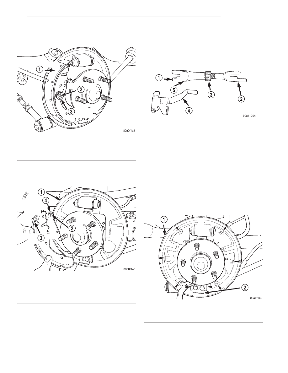
(11) Remove the hold down spring and attaching

pin (Fig. 109) from the trailing brake shoe.

(12) Remove the trailing brake shoe from the

brake support plate and the park brake actuating
lever (Fig. 110).

CLEANING AND INSPECTION

Clean metal portion of brake shoes. Check to see if

shoes are bent.

Brake shoe lining should show contact across its

entire width and from the heel to the toe of the lin-
ing, otherwise replace.

Shoes with lack of contact at toe or heel may be

improperly ground.

Clean and inspect support and adjusting screws.

Apply a thin coat of Mopar Multi-Purpose Lubricant
or equivalent to the threads of the self adjuster (Fig.
111). Replace adjusting screw if corroded.

If old springs have overheated or are damaged,

replace. Overheating indications are paint discolora-
tion or distorted end coils.

INSTALLATION

(1) Lubricate the six brake shoe contact areas on

the brake support plate and the brake shoe contact
points on the brake shoe anchor (Fig. 112) using
Mopar Multi-Purpose Lubricant or equivalent.

Fig. 109 Hold Down Spring And Pin

1 – TRAILING BRAKE SHOE
2 – ATTACHING PIN
3 – HOLD DOWN SPRING

Fig. 110 Remove /Install Trailing Brake Shoe

1 – BRAKE SUPPORT PLATE
2 – WAVE WASHER
3 – TRAILING BRAKE SHOE
4 – PARK BRAKE ACTUATING LEVER

Fig. 111 Adjuster Screw and Lever (Typical)

1 – OUTBOARD FORWARD
2 – OUTBOARD REAR
3 – STAR WHEEL
4 – SELF ADJUSTER ACTUATING LEVER
5 – SELF ADJUSTER

Fig. 112 Brake Shoe Contact Areas on Support Plate

1 – BRAKE SUPPORT PLATE
2 – BRAKE SHOE ANCHOR

JX

BRAKES

5 - 47

REMOVAL AND INSTALLATION (Continued)

(2) Install the wave washer on the pin of the park

brake actuating lever (Fig. 113).

(3) Install the trailing brake shoe on the park

brake actuating lever (Fig. 110)

(4) Install the trailing brake shoe on the brake

support plate. Install the attaching pin and hold
down spring for the trailing brake shoe (Fig. 109).

(5) Install the retaining clip attaching the park

brake actuating lever to the trailing brake shoe (Fig.
114).

(6) Install the automatic adjuster on the trailing

brake shoe and park brake actuating lever (Fig. 107).

(7) Install the leading brake shoe on the brake

support plate. Then install the attaching pin and
hold down spring for the leading brake shoe (Fig.
106).

(8) Install the brake shoe lower return spring (Fig.

105).

(9) Install the upper return spring on the brake

shoes (Fig. 104)

(10) Install the automatic adjuster actuating lever

and the actuating spring on the leading brake shoe
(Fig. 103).

(11) Manually adjust the brake shoes assemblies

out as far as possible but not so as to interfere with
brake drum installation.

(12) Install the rear brake drums on the hubs.
(13) Adjust rear brake shoes per Adjusting Rear

Brakes procedure in the service adjustments section
of the service manual.

(14) Install the wheel and tire assembly.
(15) Tighten the wheel mounting stud nuts in

proper sequence until all nuts are torqued to half
specification. Then repeat the tightening sequence to
the full specified torque of 135 N·m (100 ft. lbs.).

(16) Road test vehicle. The automatic adjuster will

continue the brake adjustment during the road test
of the vehicle.

BRAKE DRUM

NOTE: Before proceeding, review SERVICE WARN-
INGS AND CAUTIONS at the beginning of REMOVAL
AND INSTALLATION in this section.

REMOVAL

NOTE: If the vehicle has high mileage, the brake
drums may have a ridge worn in them by the brake
shoes. This ridge causes the brake drum to inter-
fere with the brake shoes thus, not allowing the
brake drum to be removed. Further clearance can
be obtained by backing off the brakes automatic
self-adjuster mechanism, using the following proce-
dure in steps (1) and (2).

(1) Remove the rubber plug from the brake sup-

port plate (Fig. 115).

(2) Insert a screwdriver, through the automatic

adjuster access hole, in the rear brake support plate
(Fig. 116). Engage screwdriver with the teeth on the
adjuster mechanism quadrant. Then rotate quadrant
so that the teeth on the quadrant are moved toward
the front of the vehicle (Fig. 116). This will back off
the adjustment of the rear brake shoes.

Fig. 113 Wave Washer Installation

1 – BRAKE SUPPORT PLATE
2 – PARK BRAKE ACTUATING LEVER
3 – WAVE WASHER

Fig. 114 Park Brake Actuating Lever Retaining Clip

Installed

1 – TRAILING BRAKE SHOE
2 – RETAINING CLIP
3 – BRAKE SUPPORT PLATE
4 – PARK BRAKE ACTUATING LEVER

5 - 48

BRAKES

JX

REMOVAL AND INSTALLATION (Continued)

(3) Remove any drum retainer clips from the

wheel mounting studs.

(4) Remove rear brake drum from the rear hub

and bearing assembly by pulling it straight off the
wheel mounting studs (Fig. 117).

INSTALLATION

(1) Slide the drum onto the mounting studs and

install rear brake drum on the rear hub and bearing
assembly.

(2) Install the wheel and tire assembly.
(3) Tighten the wheel mounting stud nuts in

proper sequence until all nuts are torqued to half
specification. Then repeat the tightening sequence to
the full specified torque of 135 N·m (100 ft. lbs.).

(4) Adjust rear brakes. The rear brakes on this

vehicle are adjusted by depressing the brake pedal as
far as possible 2 or 3 times.

DRUM BRAKE SUPPORT PLATE (REAR)

NOTE: Before proceeding, review SERVICE WARN-
INGS AND CAUTIONS at the beginning of REMOVAL
AND INSTALLATION in this section.

Fig. 115 Automatic Adjuster Access Hole Plug

1 – REAR BRAKE SUPPORT PLATE
2 – AUTOMATIC ADJUSTER ACCESS HOLE PLUG
3 – REAR SUSPENSION LATERAL LINK

Fig. 116 Backing Off Rear Brake Shoe Adjustment

1 – SCREWDRIVER
2 – ACCESS HOLE
3 – BRAKE SUPPORT PLATE

Fig. 117 Brake Drum Removal

1 – REAR BRAKE DRUM
2 – REAR BRAKE SUPPORT PLATE
3 – SHOCK ASSEMBLY
4 – REAR LATERAL ARM
5 – HUB/BEARING ASSEMBLY

JX

BRAKES

5 - 49

REMOVAL AND INSTALLATION (Continued)

REMOVAL

(1) Raise vehicle on jackstands or centered on a

hoist. See Hoisting in the Lubrication and Mainte-
nance section of this manual.

(2) Remove rear tire and wheel assembly from

vehicle.

(3) Remove the dust cap from the rear hub and

bearing assembly (Fig. 118).

(4) Remove the rear hub and bearing assembly

retaining nut (Fig. 119). Then remove the hub and
bearing assembly from the rear knuckle.

(5) Remove the rear brake shoes from the brake

support plate. Refer to Rear Brake Shoes in the
Removal And Installation Section in this group of the

service manual for the proper brake shoe assembly
removal procedure.

(6) Disconnect rear brake flex hose tube from

wheel cylinder and remove the brake flex hose
bracket from the brake support plate (Fig. 120).

(7) Position a 1/2 wrench over the retainer fingers

on the end of the parking brake cable (Fig. 121).
Compress cable housing retaining fingers and start
cable housing out of support plate (Fig. 121). Remove
wrench when retainer is free from the park brake
cable mounting hole in the rear brake support plate.
Alternate method is to use a aircraft type hose clamp
over cable housing end fitting compressing the three
fingers.

(8) Remove the 4 bolts attaching the brake support

plate to the knuckle. Separate brake support plate
from rear suspension knuckle.

INSTALLATION

(1) Install the gasket and brake support plate on

rear suspension knuckle. Torque the brake support
plate to knuckle attaching bolts to 75 N·m (55 ft.
lbs.).

(2) Insert parking brake cable end fitting into

brake support plate.

(3) Hand start hydraulic brake hose tube fitting to

wheel cylinder. Tighten tube nut to a torque of 17
N·m (145 in. lbs.).

(4) Install rear brake shoe assemblies on the brake

support plate. Refer to Rear Brake Shoes in the
Removal And Installation Section in this group of the
service manual for the proper brake shoe assembly
installation procedure.

Fig. 118 Hub And Bearing Dust Cap

1 – HUB/BEARING ASSEMBLY
2 – DUST CAP

Fig. 119 Hub And Bearing Retaining Nut

1 – RETAINING NUT
2 – SPINDLE
3 – HUB/BEARING ASSEMBLY

Fig. 120 Brake Flex Hose Tube At Wheel Cylinder

1 – BRAKE SUPPORT PLATE
2 – WHEEL CYLINDER
3 – FLEX HOSE BRACKET
4 – BOLT
5 – FLEX HOSE TUBE

5 - 50

BRAKES

JX

REMOVAL AND INSTALLATION (Continued)


Content   ..  194  195  196  197   ..