Chrysler Stratus Convertible. Manual - part 189
BRAKE DRUM MACHINING in the SERVICE PRO-
CEDURES section of this service manual group for
refacing procedures.
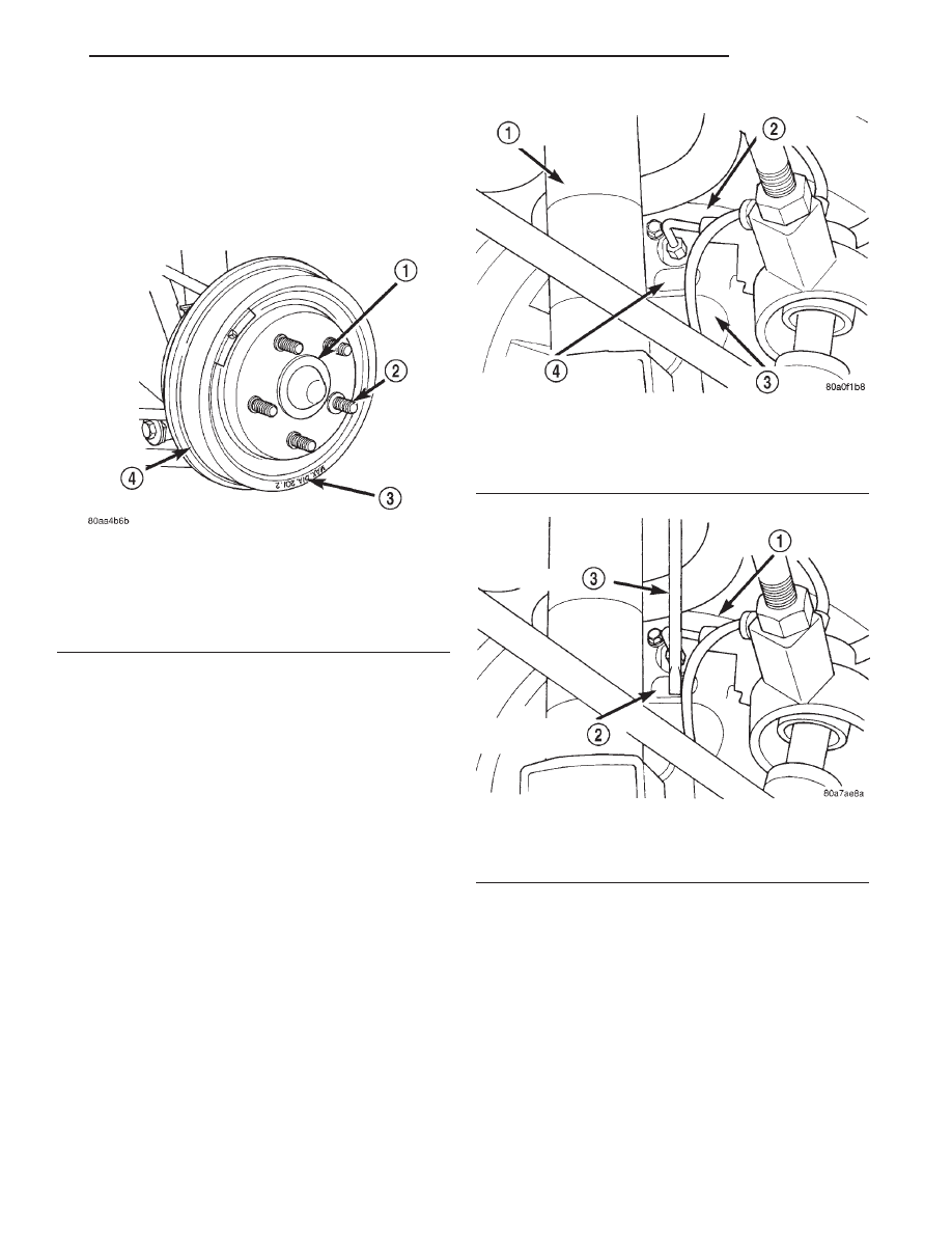
Always replace the drum if machining will cause
the diameter to exceed drum maximum diameter. All
brake drums are marked with the maximum allow-
able brake drum diameter (Fig. 31).
DRUM BRAKE AUTOMATIC ADJUSTER
Place the vehicle on a frame contact hoist with a
helper in the driver’s seat to apply the brakes. Raise
the vehicle. Remove the adjuster access hole plug,
from the rear brake support plate (Fig. 32). This will
allow access to the star wheel on the automatic
adjuster mechanism. Then, to eliminate the possibil-
ity of maximum adjustment, insert a small screw-
driver through the access hole in the support plate
(Fig. 33) and back off the adjuster star wheel approx-
imately 10 notches. It will be necessary to hold
the adjuster lever away from the star wheel to
perform this adjustment procdure.
Fully apply the brake pedal which will cause the
brake shoes to leave the anchor. Upon application of
the brake pedal, the adjuster lever should move
downward, turning the star wheel on the adjuster.
Thus, a definite rotation of the adjuster star wheel
can be observed if the automatic adjuster is working
properly. If one or more adjusters do not function
properly, the respective brake drum must be removed
for servicing of the adjuster mechanism.
BRAKE FLUID CONTAMINATION
Indications of fluid contamination are swollen or
deteriorated rubber parts.
Swollen rubber parts indicate the presence of
petroleum in the brake fluid.
To test for contamination, put a small amount of
drained brake fluid in clear glass jar. If fluid sepa-
rates into layers, there is mineral oil or other fluid
contamination of the brake fluid.
If brake fluid is contaminated, drain and thor-
oughly flush system. Replace master cylinder, propor-
tioning valve, caliper seals, wheel cylinder seals,
Antilock Brakes hydraulic unit and all hydraulic
fluid hoses.
Fig. 31 Brake Drum Maximum Diameter
Identification
1 – HUB/BEARING ASSEMBLY
2 – WHEEL MOUNTING STUDS
3 – BRAKE DRUM MAXIMUM DIAMETER MARKING
4 – REAR BRAKE DRUM
Fig. 32 Adjuster Access Hole Plug
1 – SHOCK ABSORBER
2 – BRAKE SUPPORT PLATE
3 – KNUCKLE
4 – BRAKE ADJUSTER ACCESS HOLE PLUG
Fig. 33 Accessing The Automatic Adjuster
1 – BRAKE SUPPORT PLATE
2 – BRAKE ADJUSTER ACCESS HOSE
3 – SCREWDRIVER
JX
BRAKES
5 - 19
DIAGNOSIS AND TESTING (Continued)