Chrysler Stratus Convertible. Manual - part 188


  Index      Chrysler     Chrysler Stratus Convertible - service repair manual 1995-2000 year


Search            


Content   ..  186  187  188  189   ..


Chrysler Stratus Convertible. Manual - part 188


CAUTION: Be sure the pressure test fittings being
installed into proportioning valve, have the correct
thread sizes for installation into the proportioning
valve and installation of rear brake line tube nut.

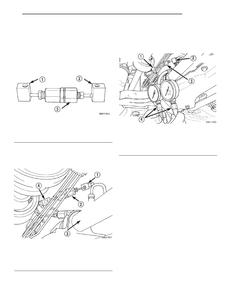
(4) Install Pressure Test Fitting, Special Tool 8187

in the inlet port of the proportioning valve (Fig. 22).
Install Pressure Test Fitting, Special Tool 8187–2 in
the outlet port of the proportioning valve (Fig. 22).
Tighten tube nuts to a torque of 17 N·m (145 in. lbs.)

(5) Install the proportioning valve with the pres-

sure test fittings installed, in the chassis brake tube
(Fig. 23). Tighten both tube nuts to a torque of 17
N·m (145 in. lbs.).

(6) Install

a

Pressure

Gauge,

Special

Tool

C-4007-A into each pressure test fitting (Fig. 24).
Bleed air out of hose from pressure test fitting to
pressure gauge, at pressure gauge to remove all
trapped air. hose.

(7) With the aid of a helper, apply pressure to the

brake pedal until reading on proportioning valve
inlet gauge, is at the pressure shown on the following
chart, PROPORTIONING VALVE APPLICATIONS
AND PRESSURE SPECIFICATIONS. Then check
the pressure reading on the proportioning valve out-
let gauge. If proportioning valve outlet pressure does
not agree with value shown on the following chart,
when inlet pressure shown on chart is obtained,
replace the proportioning valve. If proportioning
valve is within pressure specifications do not replace
proportioning valve.

(8) Check rear wheel brake shoe linings for con-

tamination or for replacement brake shoes not meet-
ing OEM brake lining material specifications. These
conditions can also be a possible cause for a prema-
ture rear wheel skid.

(9) Install proportioning valve in rear brake line

and hand tighten both tube nuts until they are fully
seated in proportioning valve.

(10) Tighten both brake line tube nuts at the pro-

portioning valve to a torque of 17 N·m (145 in. lbs.).

(11) Bleed the affected brake line. Refer to BASE

BRAKE

BLEEDING

in

the

SERVICE

PROCE-

DURES section.

Fig. 22 Pressure Test Fitting Installed In

Proportioning Valve

1 – SPECIAL TOOL 8187
2 – SPECIAL TOOL 8187–2
3 – PROPORTIONING VALVE

Fig. 23 Proportioning Valve With Pressure Test

Fittings Installed

1 – SPECIAL TOOL 8187–2
2 – PROPORTIONING VALVE
3 – STEERING GEAR
4 – SPECIAL TOOL 8187

Fig. 24 Pressure Gauges Installed On Pressure Test

Fittings

1 – PRESSURE TEST FITTING
2 – PRESSURE TEST FITTING
3 – PROPORTIONING VALVE
4 – SPECIAL TOOL C-4007–A

JX

BRAKES

5 - 15

DIAGNOSIS AND TESTING (Continued)

PROPORTIONING VALVE APPLICATIONS AND PRESSURE SPECIFICATIONS

Sales

Code

Brake System Type

Split Point

Slope

Identification

Inlet

Pressure

Outlet Pressure

BRA

14” Disc/Drum

600 psi

0.59

Bar Code

Label

1000 psi

800-900 psi

BRJ

14” Disc/Drum

W/ABS

600 psi

0.59

Bar Code

Label

1000 psi

800-900 psi

BRF

14” Disc/Disc W/ABS

500 psi

0.43

Bar Code

Label

1000 psi

600-700 psi

BRAKE ROTOR

Any servicing of the rotor requires extreme care to

maintain the rotor within service tolerances to
ensure proper brake action.

Excessive runout or wobble in a rotor can increase

pedal travel due to piston knock-back. This increases
guide pin sleeve wear due to the tendency of the cal-
iper to follow the rotor wobble.

When diagnosing a brake noise or pulsation, the

machined disc braking surface should be checked and
inspected.

BRAKING SURFACE INSPECTION

Light braking surface scoring and wear is accept-

able. If heavy scoring or warping is evident, the rotor
must be refaced or replaced. Refer to SERVICE PRO-
CEDURES in this section of this group for informa-
tion on brake rotor machining.

Excessive wear and scoring of the rotor can cause

improper lining contact on the rotor’s braking sur-
face. If the ridges on the rotor are not removed before
new brake shoes are installed, improper wear of the
shoes will result.

If a vehicle has not been driven for a period of

time, the rotor’s braking surface will rust in the
areas not covered by the brake shoes at that time.
Once the vehicle is driven, noise and chatter from
the disc brakes can result when the brakes are
applied.

Some discoloration or wear of the rotor surface is

normal and does not require resurfacing when lin-
ings are replaced. If cracks or burned spots are evi-
dent, the rotor must be replaced.

ROTOR MINIMUM THICKNESS

Measure rotor thickness at the center of the brake

shoe contact surface. Replace the rotor if it is worn
below minimum thickness or if machining the rotor
will cause its thickness to fall below specifications.

CAUTION: Do not machine the rotor if it will cause
the rotor to fall below minimum thickness.

Minimum thickness specifications are cast on the

rotor’s unmachined surface (Fig. 25). Limits can also
be found in the table at the end of this brake rotor
information.

ROTOR THICKNESS VARIATION

Thickness variation in a rotor’s braking surface

can result in pedal pulsation, chatter and surge. This
can also be caused by excessive runout in the rotor or
the hub.

Rotor thickness variation measurements should be

made in conjunction with measuring runout. Mea-
sure thickness of the brake rotor at 12 equal points
around the rotor braking surface with a micrometer
at a radius approximately 25 mm (1 inch) from edge
of rotor (Fig. 26). If thickness measurements vary by
more than 0.013 mm (0.0005 inch), the rotor should
refaced or replaced. Refer to SERVICE PROCE-
DURES in this section of this group for information
on brake rotor machining.

ROTOR RUNOUT

On-vehicle rotor runout is the combination of the

individual runout of the hub face and the runout of
the rotor. (The hub and rotor runouts are separable).

Fig. 25 Minimum Brake Rotor Thickness Markings

(Typical)

1 – ROTOR MINIMUM THICKNESS MARKING
2 – ROTOR

5 - 16

BRAKES

JX

DIAGNOSIS AND TESTING (Continued)

To measure rotor runout on the vehicle, first remove
the tire and wheel assembly. Reinstall the wheel
mounting nuts on the studs, tightening the rotor to
the hub. Mount the Dial Indicator, Special Tool
C-3339, with Mounting Adaptor, Special Tool SP-
1910 on steering arm. The dial indicator plunger
should contact braking surface of rotor approximately
25 mm (one inch) from outer edge of rotor (Fig. 27).
Check lateral runout on both sides of the rotor,
marking the low and high spots on both. Runout lim-
its can be found in the table at the end of this brake
rotor information.

If runout is in excess of the specification, check the

lateral runout of the hub face. Before removing the
rotor from the hub, place a chalk mark across both
the rotor and the one wheel stud closest to where the
high runout measurement was taken. This way, the
original mounting spot of the rotor on the hub is
indexed (Fig. 28).

Remove the rotor from the hub.

NOTE: Clean the hub face surface before checking
runout. This provides a clean surface to get an
accurate indicator reading.

Fig. 26 Checking Rotor For Thickness

1 – CALIPER

Fig. 27 Checking Rotor Runout

1 – SPECIAL TOOL SP-1910
2 – 25mm FROM EDGE
3 – DISC SURFACE
4 – SPECIAL TOOL C-3339

Fig. 28 Marking Rotor and Wheel Stud

1 – CHALK MARK

JX

BRAKES

5 - 17

DIAGNOSIS AND TESTING (Continued)

Mount Dial Indicator, Special Tool C-3339, and

Mounting Adaptor, Special Tool SP-1910, to the steer-
ing knuckle. Position the indicator stem so it contacts
the hub face near the outer diameter. Care must be
taken to position stem outside of the stud circle, but
inside of the chamfer on the hub rim (Fig. 29).

Hub runout should not exceed 0.08 mm (0.003

inch). If runout exceeds this specification, the hub

must be replaced. Refer to the SUSPENSION group
in this service manual for the hub and bearing
removal and installation procedure.

If the hub runout does not exceed this specifica-

tion, install the rotor back on the hub, aligning the
chalk marks on the rotor with a wheel mounting
stud, two studs apart from the original stud (Fig. 30).
Tighten nuts in the proper sequence and torque to
specifications.

Recheck brake rotor runout to see if the runout is

now within specifications.

If runout is not within specifications, reface or

replace the brake rotor. Refer to SERVICE PROCE-
DURES in this section of this group for information
on brake rotor machining.

BRAKE ROTOR LIMITS

Braking Rotor

Rotor Thickness

Minimum

Rotor

Thickness

Rotor

Thickness

Variation

Rotor

Runout*

Rotor Micro

Finish

Front Rotor

22.87–23.13 mm

0.900-0.911 in.

21.4 mm

0.843 in.

0.013 mm

0.0005 in.

0.13 mm

0.005 in.

15-80 RMS

Rear Rotor

8.87–9.13 mm

0.350-0.360 in.

7.25 mm

0.285 in.

0.013 mm

0.0005 in.

0.13 mm

0.005 in.

15-80 RMS

* TIR Total Indicator Reading (Measured On Vehicle)

BRAKE DRUM

With the drum off the vehicle, measure the drum

for diameter variation (oval shape). The diameter
variation of the drum braking surface must not
exceed either 0.0635 mm (0.0025 inch) in 30° or
0.0889 mm (0.0035 inch) in 360°.

Measure brake drum runout. Brake drum runout

should be checked with the drum mounted on a
brake lathe. Brake drum runout should not exceed
0.1524 mm (0.006 inch).

If either of these measurements are not within

specification, reface or replace the drum. Refer to

Fig. 29 Checking Hub Runout

1 – HUB SURFACE
2 – SPECIAL TOOL C-3339
3 – SPECIAL TOOL SP-1910

Fig. 30 Index Rotor And Wheel Stud

1 – CHALK MARK

5 - 18

BRAKES

JX

DIAGNOSIS AND TESTING (Continued)


Content   ..  186  187  188  189   ..