Chrysler Stratus Convertible. Manual - part 93
 

  Index      Chrysler     Chrysler Stratus Convertible - service repair manual 1995-2000 year


Search            


Content   ..  91  92  93  94   ..


Chrysler Stratus Convertible. Manual - part 93


NOTE: Install

the

low/reverse

reaction

plate

stepped side up.

Press down clutch pack with finger and zero dial

indicator. Low/Reverse clutch pack clearance is
0.86 to 1.52 (0.034 to 0.060 inch).

Select the proper low/reverse reaction plate to

achieve specifications:

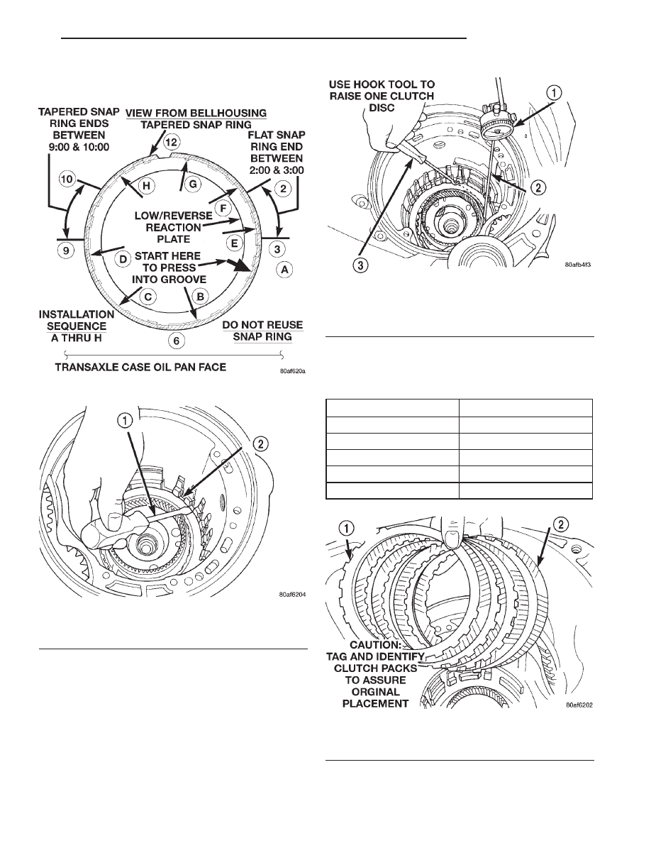
Fig. 335 Tapered Snap Ring Instructions

Fig. 336 Snap Ring Installed

1 – SCREWDRIVER
2 – TAPERED SNAP RING (INSTALL AS SHOWN)

Fig. 337 Check Low/Reverse Clutch Clearance

1 – DIAL INDICATOR
2 – DIAL INDICATOR TIP TOOL 6268
3 – HOOK TOOL

LOW/REVERSE REACTION PLATE CHART

PART NUMBER

THICKNESS

4799846AA

5.88 mm (0.232 in.)

4799847AA

6.14 mm (0.242 in.)

4799848AA

6.40 mm (0.252 in.)

4799849AA

6.66 mm (0.262 in.)

4799855AA

6.92 mm (0.273 in.)

Fig. 338 Install 2/4 Clutch Pack

1 – CLUTCH PLATE (4)
2 – CLUTCH DISC (4)

JX

TRANSAXLE

21 - 111

DISASSEMBLY AND ASSEMBLY (Continued)

NOTE: When installing the 2-4 clutch plates and
discs, the orientation should be alternated so the
pilot pads of adjacent plates do not align, refer to
(Fig. 339).

NOTE: Verify that Miller Tool 5058 is centered prop-
erly to the 2/4 clutch retainer before depressing the
tool.

Fig. 339 Stagger 2/4 Clutch Plate Pads

1 – PILOT PADS
2 – LUGS

Fig. 340 Install 2/4 Clutch Return Spring

1 – 2/4 CLUTCH RETURN SPRING

Fig. 341 Proper Orientation of 2/4 Clutch Retainer

and Spring

1 – NOTE POSITION
2 – RETURN SPRING
3 – 2/4 CLUTCH RETAINER

Fig. 342 Install 2/4 Clutch Retainer

1 – 2/4 CLUTCH RETAINER
2 – 2/4 CLUTCH RETURN SPRING

21 - 112

TRANSAXLE

JX

DISASSEMBLY AND ASSEMBLY (Continued)

Press down clutch pack with finger and zero dial

indicator. The 2/4 clutch pack clearance is 0.76 to
2.64mm (0.030 to 0.104 inch). 
If not within specifi-
cations, the clutch is not assembled properly. There
is no adjustment for the 2/4 clutch clearance.

Fig. 343 Install 2/4 Clutch Retainer Snap Ring

1 – TOOL 5058
2 – SCREWDRIVER
3 – SNAP RING
4 – 2/4 CLUTCH RETAINER

Fig. 344 Check 2/4 Clutch Clearance

1 – DIAL INDICATOR
2 – HOOK TOOL
3 – DIAL INDICATOR TIP TOOL 6268

Fig. 345 Install Rear Sun Gear

1 – #7 NEEDLE BEARING
2 – REAR SUN GEAR

Fig. 346 Install Front Carrier and Rear Annulus

Assembly

1 – #6 NEEDLE BEARING
2 – FRONT CARRIER AND REAR ANNULUS ASSEMBLY (TWIST

AND PULL OR PUSH TO REMOVE OR INSTALL).

JX

TRANSAXLE

21 - 113

DISASSEMBLY AND ASSEMBLY (Continued)

DETERMINING No. 4 THRUST PLATE
THICKNESS—INPUT SHAFT END PLAY

To determine the proper thickness of the No. 4

thrust plate, select the thinnest No. 4 thrust plate.
Using petrolatum (Fig. 348) to hold thrust plate in
position, install input clutch assembly. Be sure the
input clutch assembly is completely seated (Fig. 349).

CAUTION: If view through input speed sensor hole
is not as shown above, the input clutches assembly
is not seated properly.

Remove the oil pump O-ring (Fig. 350). You will be

able to install and remove the oil pump and gasket
very easily to select the proper No. 4 thrust plate.

NOTE: Use screw-in dowels or phillips-head screw-
drivers to align pump to case.

CAUTION: Be sure to reinstall O-ring on oil pump
after selecting the proper No. 4 thrust plate.

Fig. 347 Install Front Sun Gear Assembly

1 – FRONT SUN GEAR ASSEMBLY
2 – #4 THRUST WASHER (FOUR TABS)

Fig. 348 Select Thinnest No. 4 Thrust Plate

1 – OVERDRIVE SHAFT ASSEMBLY
2 – #4 THRUST PLATE (SELECT)
3 – 3 DABS OF PETROLATUM FOR RETENTION

Fig. 349 View Through Input Speed Sensor Hole

1 – INPUT CLUTCHES RETAINER
2 – INPUT (TURBINE) SPEED SENSOR HOLE
3 – OIL COOLER NIPPLES

Fig. 350 Remove Oil Pump O-Ring

1 – OIL PUMP ASSEMBLY
2 – O-RING

21 - 114

TRANSAXLE

JX

DISASSEMBLY AND ASSEMBLY (Continued)


Content   ..  91  92  93  94   ..