Chrysler Stratus Convertible. Manual - part 67
T/C REGULATOR VALVE
The torque converter regulator valve slightly regu-
lates the flow of fluid to the torque converter.
LOW/REVERSE SWITCH VALVE
The low/reverse clutch is applied from different
sources, depending on whether low (1st) gear or
reverse is selected. The low/reverse switch valve
alternates positions depending on from which direc-
tion fluid pressure is applied. By design, when the
valve is shifted by fluid pressure from one channel,
the opposing channel is blocked. The switch valve
alienates the possibility of a sticking ball check, thus
providing consistent application of the low/reverse
clutch under all operating conditions.
VENT RESERVOIR CHECK VALVE
The vent reservoir check valve is designed for
quick venting during garage shifts to prevent the
overdrive and reverse clutches from dragging. Inad-
vertent motion of the reverse/overdrive (push/pull)
piston can be caused by the unbalanced centrifugal
forces in the reverse and overdrive chambers. By
linking the overdrive and reverse vents to the vent
reservoir at the manual valve, an equal residual
pressure will be maintained, thus balancing the cen-
trifugal forces in the reverse and the overdrive cham-
bers.
ACCUMULATORS
DESCRIPTION
The 41te underdrive, overdrive, low/reverse, and
2/4 clutch hydraulic circuits each contain an accumu-
lator. An accumulator typically consists of a piston,
seals, return spring(s), and a cover or plug. The over-
drive
and
underdrive
accumulators
are
located
within the transaxle case, and are retained by the
valve body (Fig. 6).
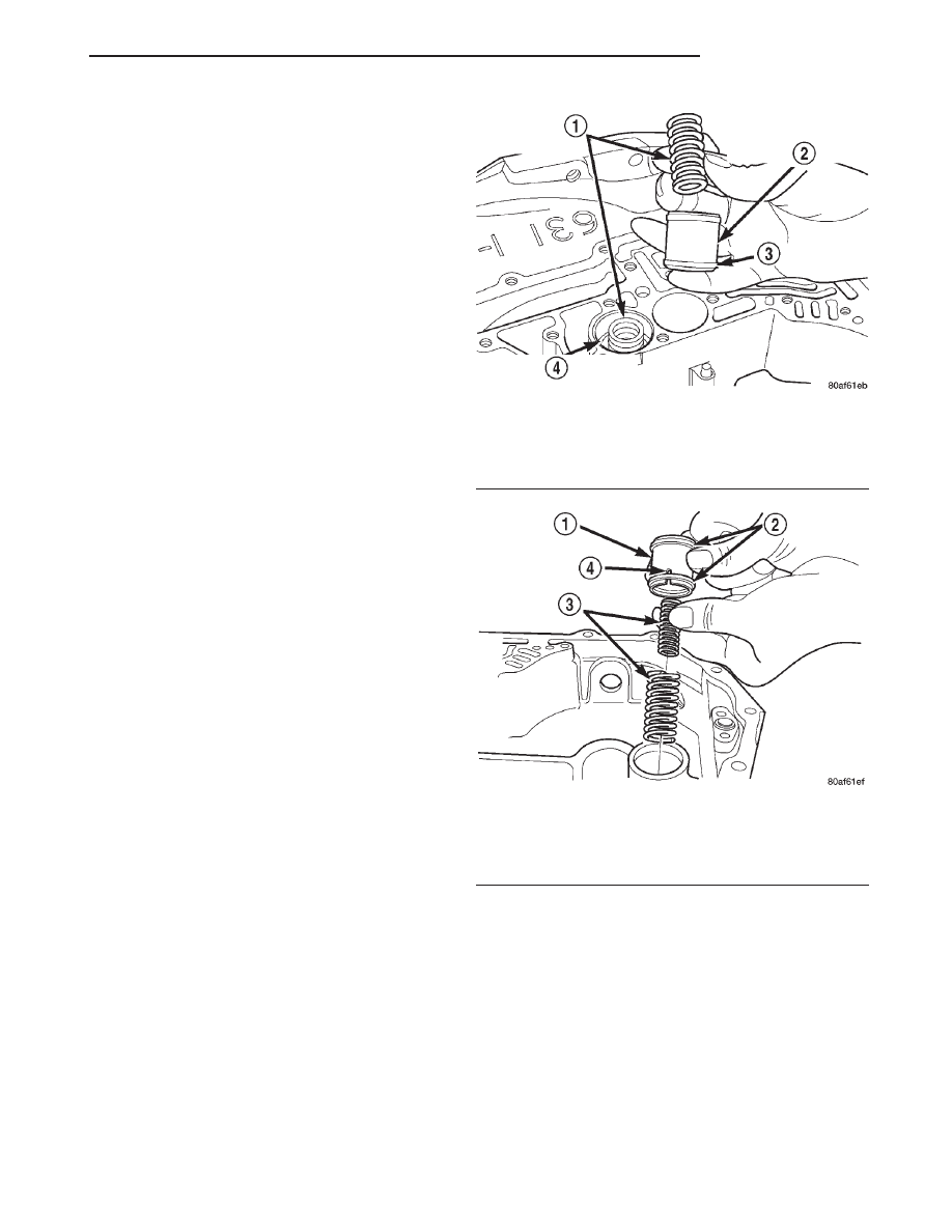
The low reverse accumulator (Fig. 7) is also located
within the transaxle case, but the assembly is
retained by a cover and a snap-ring.
The 2/4 accumulator is located in the valve body. It
is retained by a cover and retaining screws (Fig. 8).
OPERATION
The function of an accumulator is to cushion the
application of a frictional clutch element. When pres-
surized fluid is applied to a clutch circuit, the appli-
cation force is dampened by fluid collecting in the
respective accumulator chamber against the piston
and spring(s). The intended result is a smooth, firm
clutch application.
INPUT CLUTCHES
DESCRIPTION
Three hydraulically applied input clutches are used
to drive planetary components. The underdrive, over-
drive, and reverse clutches are considered input
clutches and are contained within the input clutch
assembly (Fig. 9). The input clutch assembly also
contains:
• Input shaft
• Input hub
• Clutch retainer
• Underdrive piston
Fig. 6 Underdrive and Overdrive Accumulators
1 – RETURN SPRING
2 – UNDERDRIVE CLUTCH ACCUMULATOR
3 – SEAL RING (2)
4 – OVERDRIVE CLUTCH ACCUMULATOR
Fig. 7 Low/Reverse Accumulator Assembly
1 – ACCUMULATOR PISTON
2 – SEAL RINGS
3 – RETURN SPRINGS
4 – (NOTE NOTCH)
JX
TRANSAXLE
21 - 7
DESCRIPTION AND OPERATION (Continued)