Chrysler Stratus Convertible. Manual - part 66
 

  Index      Chrysler     Chrysler Stratus Convertible - service repair manual 1995-2000 year


Search            


Content   ..  64  65  66  67   ..


Chrysler Stratus Convertible. Manual - part 66


The 41TE (Fig. 1) is a four-speed transaxle that is

a conventional hydraulic/mechanical assembly with
an integral differential, and is controlled with adap-
tive electronic controls and monitors. The hydraulic
system of the transaxle consists of the transaxle
fluid, fluid passages, hydraulic valves, and various
line pressure control components. An input clutch
assembly which houses the underdrive, overdrive,
and reverse clutches is used. It also utilizes separate
holding clutches: 2nd/4th gear and Low/Reverse. The
primary mechanical components of the transaxle con-
sist of the following:

• Three multiple disc input clutches

• Two multiple disc holding clutches

• Four hydraulic accumulators

• Two planetary gear sets

• Hydraulic oil pump

• Valve body

• Solenoid/Pressure switch assembly

• Integral differential assembly
Control of the transaxle is accomplished by fully

adaptive electronics. Optimum shift scheduling is
accomplished through continuous real-time sensor
feedback information provided to the Transmission
Control Module (TCM).

The TCM is the heart of the electronic control sys-

tem and relies on information from various direct
and indirect inputs (sensors, switches, etc.) to deter-
mine driver demand and vehicle operating condi-
tions. With this information, the TCM can calculate
and perform timely and quality shifts through vari-
ous output or control devices (solenoid pack, trans-
mission control relay, etc.).

The TCM also performs certain self-diagnostic

functions and provides comprehensive information
(sensor data, DTC’s, etc.) which is helpful in proper
diagnosis and repair. This information can be viewed
with the DRB scan tool.

TRANSAXLE IDENTIFICATION

The 41TE transaxle identification code is a series

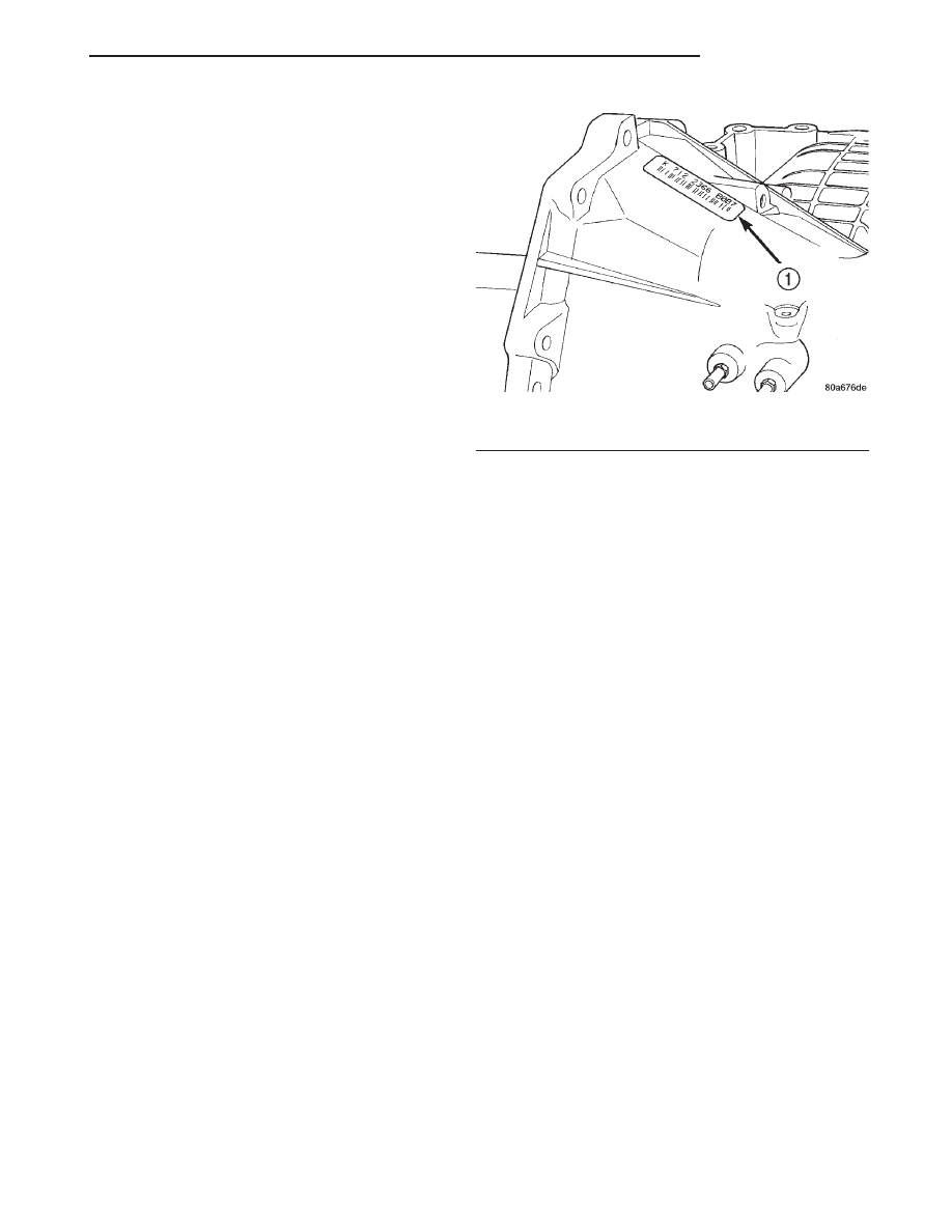
of digits printed on a bar-code label that is fixed to
the transaxle case as shown in (Fig. 2).

For example, the identification code K 821 1125

1316 can be broken down as follows:

• K = Kokomo Transmission Plant

• 821 = Last three digits of the transaxle part

number

• 1125 = Build date

• 1316 = Build sequence number
If the tag is not legible or missing, the “PK” num-

ber, which is stamped into the transaxle case behind
the transfer gear cover, can be referred to for identi-
fication. This number differs slightly in that it con-
tains the entire transaxle part number, rather than
the last three digits.

OPERATION

Transmission output is directed to an integral dif-

ferential by a transfer gear system in the following
input-to-output ratios:

First . . . . . . . . . . . . . . . . . . . . . . . . . . . . . . 2.84 : 1
Second . . . . . . . . . . . . . . . . . . . . . . . . . . . . . 1.57 : 1
Third . . . . . . . . . . . . . . . . . . . . . . . . . . . . . . 1.00 : 1
Overdrive . . . . . . . . . . . . . . . . . . . . . . . . . . 0.69 : 1
Reverse . . . . . . . . . . . . . . . . . . . . . . . . . . . . 2.21 : 1

Final Drive Ratio (FDR) for all 2.5L equipped JX

models is 3.91

FLUID REQUIREMENT

NOTE: Refer

to

the

maintenance

schedules

in

Group 0, Lubrication and Maintenance for the rec-
ommended maintenance (fluid/filter change) inter-
vals for this transaxle.

NOTE: Refer to Service Procedures in this group
for fluid level checking procedures.

NOTE: The transmission and differential sump have
a common oil sump with an opening between the
two.

DESCRIPTION

Mopar

t ATF+4 (Automatic Transmission Fluid-

Type 9602) is required in this transaxle. Substitute
fluids can induce torque converter clutch shudder.

Mopar

t ATF+4 (Automatic Transmission Fluid-

Type 9602) when new is red in color. The ATF is dyed
red so it can be identified from other fluids used in

Fig. 2 Transaxle Identification Label

1 – IDENTIFICATION TAG

JX

TRANSAXLE

21 - 3

DESCRIPTION AND OPERATION (Continued)

the vehicle such as engine oil or antifreeze. The red
color is not permanent and is not an indicator of fluid
condition. As the vehicle is driven, the ATF will begin
to look darker in color and may eventually become
brown. This is normal. A dark brown/black fluid
accompanied with a burnt odor and/or deterioration
in shift quality may indicate fluid deterioration or
transmission component failure.

FLUID ADDITIVES

DaimlerChrysler strongly recommends against the

addition of any fluids to the transmission, other than
those automatic transmission fluids listed above.
Exceptions to this policy are the use of special dyes
to aid in detecting fluid leaks.

Various “special” additives and supplements exist

that claim to improve shift feel and/or quality. These
additives and others also claim to improve converter
clutch operation and inhibit overheating, oxidation,
varnish, and sludge. These claims have not been sup-
ported to the satisfaction of DaimlerChrysler and these
additives must not be used. The use of transmission
“sealers” should also be avoided, since they may
adversely affect the integrity of transmission seals.

TORQUE CONVERTER

DESCRIPTION

The torque converter is located in the bellhousing

area of the transaxle, between the engine and tran-
saxle. The torque converter is a fluid coupling that
transmits torque from the engine drive plate to the
input shaft of the transaxle. The torque converter
consists of four main components (Fig. 3) :

• Impeller

• Turbine

• Stator

• Converter Clutch assembly

OPERATION

The converter impeller (driving member), which is

integral to the converter housing and bolted to the
engine drive plate, rotates at engine speed. The con-
verter turbine (driven member), which reacts from
fluid pressure generated by the impeller, rotates and
turns the transmission input shaft.

Torque is transmitted by fluid passing through

curved vanes in both the impeller and turbine. Since
the coupling is produced by transmission fluid, the
turbine can slip or turn slower than the impeller.

The stator contains a one-way overrunning clutch,

which free-wheels when the impeller and turbine are
rotating at the same speed. However, the stator stops
when speed reduction or torque increase take place.
When the stator stops, it changes the direction of the
fluid leaving the turbine vanes. This directs fluid

back into the impeller with greater force, resulting in
torque multiplication.

The torque converter clutch is hydraulically oper-

ated and controlled by the TCM. It consists of a pis-
ton

and

a

frictional

disc

that

form

a

direct

mechanical link between the impeller and turbine
when slippage is inefficient or unnecessary.

The torque converter hub drives the transmission

oil pump.

ELECTRONICALLY MODULATED CONVERTER
CLUTCH

In order to reduce heat build-up in the transmis-

sion and buffer the powertrain against torsional
vibrations, the TCM can duty cycle the LR/CC sole-
noid to achieve a smooth application of the torque
converter clutch. This function, also referred as
“Electronically Modulated Converter Clutch (EMCC),
can occur at various times depending on the follow-
ing variables:

• Shift lever position

• Current gear range

• Transmission fluid temperature

• Engine coolant temperature

Fig. 3 Torque Converter Assembly

1 – TURBINE
2 – IMPELLER
3 – HUB
4 – STATOR
5 – CONVERTER CLUTCH DISC
6 – DRIVE PLATE

21 - 4

TRANSAXLE

JX

DESCRIPTION AND OPERATION (Continued)

• Input speed

• Throttle angle

• Engine speed
The TCM controls the torque converter by way of

internal logic software. The programming of the soft-
ware provides the TCM with fine control over the
LR/CC solenoid. There are four output logic states
that can be applied as follows:

• No EMCC

• Partial EMCC

• Full EMCC

• Gradual-to-no EMCC

NO EMCC

Under No EMCC conditions, the L/R Solenoid is

OFF. There are several conditions that can result in
NO EMCC operations. No EMCC can be initiated
due to a fault in the transaxle or because the TCM
does not see the need for EMCC under current driv-
ing conditions.

PARTIAL EMCC

Partial EMCC operation modulates the L/R Sole-

noid (duty cycle) to obtain partial torque converter
clutch application. Partial EMCC operation is main-
tained until Full EMCC is called for an actuated.
During Partial EMCC some slip does occur. Partial
EMCC will usually occur at low speeds, low load and
light throttle situations.

FULL EMCC

During Full EMCC operation, the TCM increases

the L/R Solenoid duty cycle to full ON after Partial
EMCC control brings the engine speed within the
desired slip range of transaxle input speed relative to
engine rpm.

GRADUAL-TO-NO EMCC

This operation is to soften the change from Full or

Partial EMCC to No EMCC. This is done at mid-
throttle by decreasing the L/R Solenoid duty cycle.

OIL PUMP

DESCRIPTION

The oil pump is located in the pump housing inside

the bell housing of the transaxle case. The oil pump
consists of an inner and outer gear, a housing, and a
cover that also serves as the reaction shaft support.

OPERATION

As the torque converter rotates, the converter hub

rotates the inner and outer gears. As the gears rotate,
the clearance between the gear teeth increases in the
crescent area, and creates a suction at the inlet side
of the pump. This suction draws fluid through the

pump inlet from the oil pan. As the clearance between
the gear teeth in the crescent area decreases, it forces
pressurized fluid into the pump outlet and to the
valve body.

VALVE BODY

DESCRIPTION

The valve body assembly consists of a cast alumi-

num valve body, a separator plate, and transfer
plate. The valve body contains valves and check balls
that control fluid delivery to the torque converter
clutch, solenoid/pressure switch assembly, and fric-
tional clutches. The valve body contains the following
components (Fig. 5) :

• Regulator valve

• Solenoid switch valve

• Manual valve

• Converter clutch switch valve

• Converter clutch control valve

• Torque converter regulator valve

• Low/Reverse switch valve

• Vent reservoir check valve
In addition, the valve body also contains the ther-

mal valve, #2,3&4 check balls, the #5 (overdrive)
check valve and the 2/4 accumulator assembly. Refer
to Valve Body Disassembly & Assembly for the loca-
tion of these components.

Fig. 4 Oil Pump Assembly

1 – PUMP HOUSING
2 – OUTER PUMP GEAR
3 – INNER PUMP GEAR
4 – REACTION SHAFT SUPPORT
5 – SEAL RINGS (4)
6 – REACTION SHAFT
7 – CRESCENT

JX

TRANSAXLE

21 - 5

DESCRIPTION AND OPERATION (Continued)

OPERATION

NOTE: Refer to the Hydraulic Schematics for a
visual aid in determining valve location, operation
and design.

REGULATOR VALVE

The regulator valve controls hydraulic pressure in

the transaxle. It receives unregulated pressure from
the pump, which works against spring tension to
maintain oil at specific pressures. A system of sleeves
and ports allows the regulator valve to work at one of
three predetermined pressure levels. Regulated oil
pressure is also referred to as “line pressure.”

SOLENOID SWITCH VALVE

The solenoid switch valve controls line pressure

from the LR/CC solenoid. In one position, it allows
the low/reverse clutch to be pressurized. In the other,
it directs line pressure to the converter control and
converter clutch valves.

MANUAL VALVE

The manual valve is operated by the mechanical

shift linkage. Its primary responsibility is to send

line pressure to the appropriate hydraulic circuits
and solenoids. The valve has three operating ranges
or positions.

CONVERTER CLUTCH SWITCH VALVE

The main responsibility of the converter clutch

switch valve is to control hydraulic pressure applied
to the front (off) side of the converter clutch piston.
Line pressure from the regulator valve is fed to the
torque converter regulator valve, where it passes
through the valve, and is slightly regulated. The
pressure is then directed to the converter clutch
switch valve and to the front side of the converter
clutch piston. This pressure pushes the piston back
and disengages the converter clutch.

CONVERTER CLUTCH CONTROL VALVE

The converter clutch control valve controls the

back (on) side of the torque converter clutch. When
the TCM energizes or modulates the LR/CC solenoid
to apply the converter clutch piston, both the con-
verter clutch control valve and the converter control
valve move, allowing pressure to be applied to the
back side of the clutch.

Fig. 5 Valve Body Assembly

1 – VALVE BODY
2 – T/C REGULATOR VALVE
3 – L/R SWITCH VALVE
4 – VENT RESERVOIR CHECK VALVE
5 – CONVERTER CLUTCH CONTROL VALVE

6 – MANUAL VALVE
7 – CONVERTER CLUTCH SWITCH VALVE
8 – SOLENOID SWITCH VALVE
9 – REGULATOR VALVE

21 - 6

TRANSAXLE

JX

DESCRIPTION AND OPERATION (Continued)


Content   ..  64  65  66  67   ..