Chrysler Stratus Convertible. Manual - part 68
 

  Index      Chrysler     Chrysler Stratus Convertible - service repair manual 1995-2000 year


Search            


Content   ..  66  67  68  69   ..


Chrysler Stratus Convertible. Manual - part 68


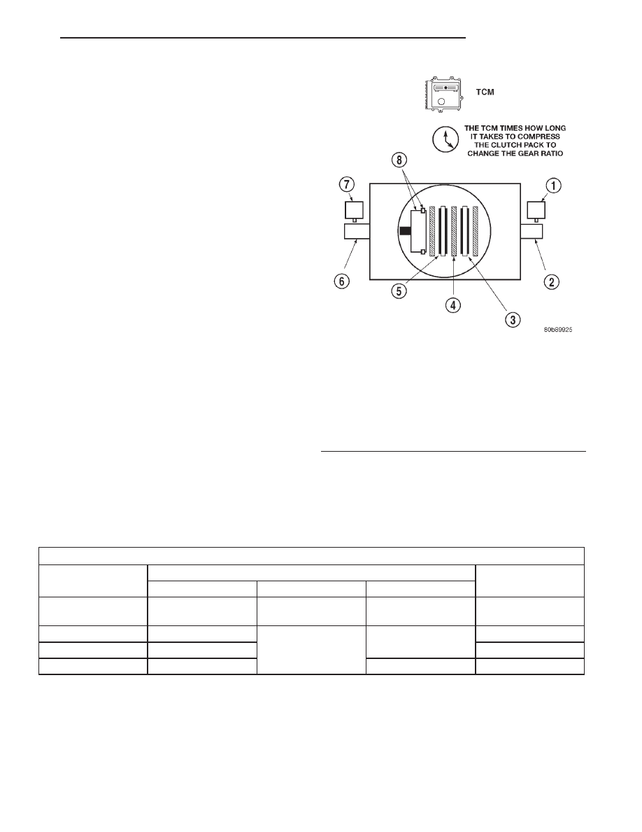
CLUTCH VOLUME INDEX (CVI)

An important function of the TCM is to monitor

Clutch Volume Index (CVI). CVIs represent the vol-
ume of fluid needed to compress a clutch pack.

The TCM monitors gear ratio changes by monitor-

ing the Input and Output Speed Sensors. The Input,
or Turbine Speed Sensor sends an electrical signal to
the TCM that represents input shaft rpm. The Out-
put Speed Sensor provides the TCM with output
shaft speed information.

By comparing the two inputs, the TCM can deter-

mine transaxle gear ratio. This is important to the
CVI calculation because the TCM determines CVIs
by monitoring how long it takes for a gear change to
occur (Fig. 14).

Gear ratios can be determined by using the DRB

Scan Tool and reading the Input/Output Speed Sen-
sor values in the “Monitors” display. Gear ratio can
be obtained by dividing the Input Speed Sensor value
by the Output Speed Sensor value.

For example, if the input shaft is rotating at 1000

rpm and the output shaft is rotating at 500 rpm,
then the TCM can determine that the gear ratio is
2:1. In direct drive (3rd gear), the gear ratio changes
to 1:1. The gear ratio changes as clutches are applied
and released. By monitoring the length of time it
takes for the gear ratio to change following a shift
request, the TCM can determine the volume of fluid
used to apply or release a friction element.

The volume of transmission fluid needed to apply

the friction elements are continuously updated for
adaptive controls. As friction material wears, the vol-
ume of fluid need to apply the element increases.

Certain mechanical problems within the clutch

assemblies (broken return springs, out of position
snap rings, excessive clutch pack clearance, improper

assembly, etc.) can cause inadequate or out-of-range
clutch volumes. Also, defective Input/Output Speed
Sensors and wiring can cause these conditions. The
following chart identifies the appropriate clutch vol-
umes and when they are monitored/updated:

CLUTCH VOLUMES

Clutch

When Updated

Proper Clutch

Volume

Shift Sequence

Oil Temperature

Throttle Angle

L/R

2-1 or 3-1 coast

downshift

> 70°

< 5°

35 to 83

2/4

1-2 shift

> 110°

5 - 54°

20 to 77

OD

2-3 shift

48 to 150

UD

4-3 or 4-2 shift

> 5°

24 to 70

Fig. 14 Example of CVI Calculation

1 – OUTPUT SPEED SENSOR
2 – OUTPUT SHAFT
3 – CLUTCH PACK
4 – SEPARATOR PLATE
5 – FRICTION DISCS
6 – INPUT SHAFT
7 – INPUT SPEED SENSOR
8 – PISTON AND SEAL

JX

TRANSAXLE

21 - 11

DESCRIPTION AND OPERATION (Continued)

SHIFT SCHEDULES

As mentioned earlier, the TCM has programming

that allows it to select a variety of shift schedules.
Shift schedule selection is dependent on the follow-
ing:

• Shift lever position

• Throttle position

• Engine load

• Fluid temperature

• Software level
As driving conditions change, the TCM appropri-

ately adjusts the shift schedule. Refer to the follow-
ing chart to determine the appropriate operation
expected, depending on driving conditions.

Schedule

Condition

Expected Operation

Extreme Cold

Oil temperature at start-up below
-16° F

Park, Reverse, Neutral and 2nd
gear only (prevents shifting which
may fail a clutch with frequent
shifts)

Cold

Oil temperature at start-up above
-12° F and below 36° F

– Delayed 2-3 upshift
(approximately 22-31 mph)

– Delayed 3-4 upshift (45-53 mph)

– Early 4-3 costdown shift
(approximately 30 mph)

– Early 3-2 coastdown shift
(approximately 17 mph)

– High speed 4-2, 3-2, 2-1 kickdown
shifts are prevented

– No EMCC

Warm

Oil temperature at start-up above
36° F and below 80 degree F

– Normal operation (upshift,
kickdowns, and coastdowns)

– No EMCC

Hot

Oil temperature at start-up above
80° F

– Normal operation (upshift,
kickdowns, and coastdowns)

– Full EMCC, no PEMCC except to
engage FEMCC (except at closed
throttle at speeds above 70-83 mph)

Overheat

Oil temperature above 240° F or
engine coolant temperature above
244° F

– Delayed 2-3 upshift (25-32 mph)

– Delayed 3-4 upshift (41-48 mph)

– 3rd gear FEMCC from 30-48 mph

– 3rd gear PEMCC from 27-31 mph

Super Overheat

Oil temperature above 260° F

– All “Overheat” shift schedule
features apply

– 2nd gear PEMCC above 22 mph

– Above 22 mph the torque
converter will not unlock unless the
throttle is closed or if a wide open
throttle 2nd PEMCC to 1 kickdown
is made

21 - 12

TRANSAXLE

JX

DESCRIPTION AND OPERATION (Continued)

TRANSMISSION CONTROL RELAY

DESCRIPTION

The transmission control relay is located in the

Power Distribution Center (PDC) on the left side of
the engine compartment (Fig. 15).

OPERATION

The relay is supplied fused B+ voltage, energized

by the TCM, and is used to supply power to the sole-
noid pack when the transmission is in normal oper-
ating mode. When the relay is “off”, no power is
supplied to the solenoid pack and the transmission is
in “limp-in” mode. After a controller reset (ignition
key turned to the “run” position or after cranking
engine), the TCM energizes the relay. Prior to this,
the TCM verifies that the contacts are open by check-
ing for no voltage at the switched battery terminals.
After this is verified, the voltage at the solenoid pack
pressure switches is checked. After the relay is ener-
gized, the TCM monitors the terminals to verify that
the voltage is greater than 3 volts.

SOLENOID/PRESSURE SWITCH ASSEMBLY

DESCRIPTION

The Solenoid/Pressure Switch Assembly (Fig. 16) is

external to the transaxle and mounted to the tran-
saxle case. The assembly consists of four solenoids
that control hydraulic pressure to the LR/CC, 2/4,
OD, and UD friction elements. The reverse clutch is

controlled by line pressure from the manual valve in
the valve body. The solenoids are contained within
the Solenoid/Pressure Switch Assembly, and can only
be serviced by replacing the assembly.

The

solenoid

assembly

also

contains

pressure

switches that monitor and send hydraulic circuit infor-
mation to the TCM. Likewise, the pressure switches
can only be service by replacing the assembly.

OPERATION

SOLENOIDS

The solenoids receive electrical power from the

Transmission Control Relay through a single wire.
The TCM energizes or operates the solenoids individ-
ually by grounding the return wire of the solenoid
needed. When a solenoid is energized, the solenoid
valve shifts, and a fluid passage is opened or closed
(vented or applied), depending on its default operat-
ing state. The result is an apply or release of a fric-
tional element.

The 2/4 and UD solenoids are normally applied,

which by design allow fluid to pass through in their
relaxed or “off” state. This allows transaxle limp-in
(P,R,N,2) in the event of an electrical failure.

The continuity of the solenoids and circuits are

periodically tested. Each solenoid is turned on or off
depending on its current state. An inductive spike
should be detected by the TCM during this test. It no
spike is detected, the circuit is tested again to verify
the failure. In addition to the periodic testing, the
solenoid circuits are tested if a speed ratio or pres-
sure switch error occurs.

Fig. 15 Transmission Control Relay Location

(Typical)

1 – TRANSMISSION CONTROL RELAY
2 – PDC
3 – TCM

Fig. 16 Solenoid/Pressure Switch Assembly

1 – SOLENOID AND PRESSURE SWITCH ASSEMBLY

JX

TRANSAXLE

21 - 13

DESCRIPTION AND OPERATION (Continued)

PRESSURE SWITCHES

The TCM relies on three pressure switches to mon-

itor fluid pressure in the L/R, 2/4, and OD hydraulic
circuits. The primary purpose of these switches is to
help the TCM detect when clutch circuit hydraulic
failures occur. The range for the pressure switch clos-
ing and opening points is 11-23 psi. Typically the
switch opening point will be approximately one psi
lower than the closing point. For example, a switch
may close at 18 psi and open at 17 psi. The switches
are continuously monitored by the TCM for the cor-
rect states (open or closed) in each gear as shown in
the following chart:

A Diagnostic Trouble Code (DTC) will set if the

TCM senses any switch open or closed at the wrong
time in a given gear.

The TCM also tests the 2/4 and OD pressure

switches when they are normally off (OD and 2/4 are
tested in 1st gear, OD in 2nd gear, and 2/4 in 2nd
gear). The test simply verifies that they are opera-
tional, by looking for a closed state when the corre-
sponding element is applied. Immediately after a
shift into 1st, 2nd, or 3rd gear with the engine speed
above 1000 rpm, the TCM momentarily turns on ele-
ment pressure to the 2/4 and/or OD clutch circuits to
identify that the appropriate switch has closed. If it
doesn’t close, it is tested again. If the switch fails to
close the second time, the appropriate Diagnostic
Trouble Code (DTC) will set.

TRANSMISSION RANGE SENSOR

DESCRIPTION

The Transmission Range Sensor (TRS) is mounted

to the top of the valve body inside the transaxle and
can only be serviced by removing the valve body. The
electrical connector extends through the transaxle
case (Fig. 17).

The Transmission Range Sensor (TRS) has four

switch contacts that monitor shift lever position and
send the information to the TCM.

The TRS also has an integrated temperature sen-

sor (thermistor) that communicates transaxle tem-
perature to the TCM and PCM (Fig. 18).

OPERATION

The Transmission Range Sensor (TRS) (Fig. 17)

communicates shift lever position (SLP) to the TCM
as a combination of open and closed switches. Each
shift lever position has an assigned combination of
switch states (open/closed) that the TCM receives

PRESSURE SWITCH STATES

GEAR

L/R

2/4

OD

R

OP

OP

OP

P/N

CL

OP

OP

1st

CL

OP

OP

2nd

OP

CL

OP

D

OP

OP

CL

OD

OP

CL

CL

OP = OPEN

CL = CLOSED

Fig. 17 Transmission Range Sensor (TRS) Location

1 – TRANSMISSION RANGE SENSOR

Fig. 18 Transmission Temperature Sensor

1 – TRANSMISSION RANGE SENSOR
2 – TEMPERATURE SENSOR

21 - 14

TRANSAXLE

JX

DESCRIPTION AND OPERATION (Continued)


Content   ..  66  67  68  69   ..