Chrysler Stratus Convertible. Manual - part 13
(10) Connect negative battery cable to battery or
auxiliary jumper terminal.
(11) Use the DRB scan tool ASD Fuel System Test
to pressurize the fuel system. Check for leaks.
REMOVAL AND INSTALLATION
AUTOMATIC SHUTDOWN RELAY
The relay is located in the Power Distribution Cen-
ter (PDC) (Fig. 10). For the location of the relay
within the PDC, refer to the PDC cover for location.
Check electrical terminals for corrosion and repair as
necessary.
FUEL PUMP RELAY
The fuel pump relay is located in the PDC. The
inside top of the PDC cover has a label showing relay
and fuse location.
FUEL PUMP MODULE
WARNING: RELEASE FUEL SYSTEM PRESSURE
BEFORE SERVICING FUEL SYSTEM COMPONENTS.
SERVICE VEHICLES IN WELL VENTILATED AREAS
AND AVOID IGNITION SOURCES. NEVER SMOKE
WHILE SERVICING THE VEHICLE.
REMOVAL
(1) Remove fuel filler cap and perform Fuel Sys-
tem Pressure Release procedure.
(2) Disconnect
negative
cable
from
auxiliary
jumper terminal.
(3) Remove fuel tank, refer to the Fuel Tank
removal section.
(4) Disconnect fuel filter lines from fuel pump
module.
(5) Clean top of tank to remove loose dirt and
debris.
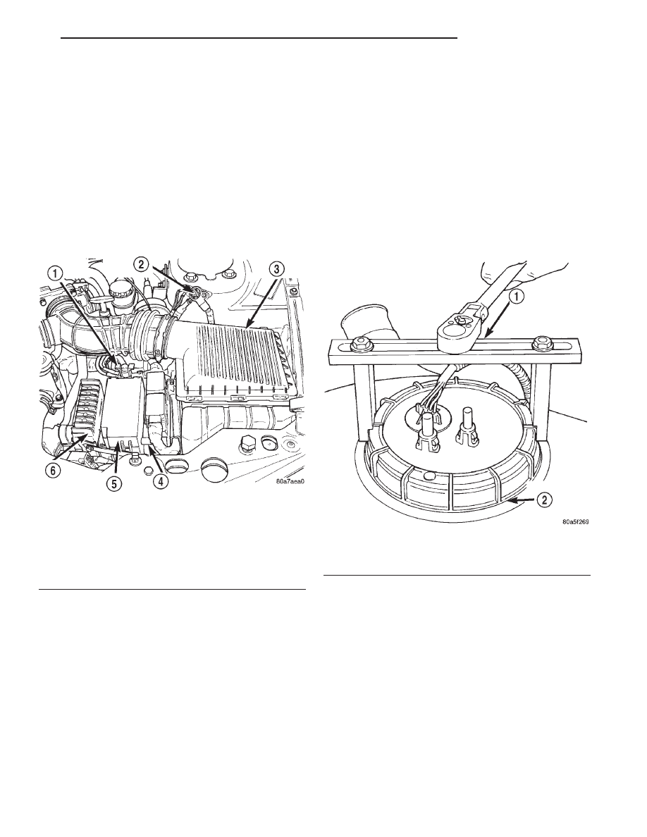
(6) Using Special Tool #6856 Fuel Pump Module
Ring Spanner, remove locknut to release pump mod-
ule (Fig. 11).
WARNING:
THE FUEL RESERVOIR OF THE FUEL
PUMP MODULE DOES NOT EMPTY OUT WHEN THE
TANK IS DRAINED. THE FUEL IN THE RESERVOIR
MAY SPILL OUT WHEN THE MODULE IS REMOVED.
(7) Remove fuel pump module and O-ring from
tank (Fig. 12). Discard O-ring.
INSTALLATION
(1) Wipe seal area of tank clean. Place a new
O-ring on the ledge between the tank threads and
the pump module opening.
(2) Position fuel pump module in tank. Make sure
the alignment tab on the underside of the pump mod-
ule flange sits in the corresponding notch in the fuel
tank.
Fig. 10 Power Distribution Center (PDC)
1 – BATTERY POSITIVE
2 – BATTERY GROUND
3 – AIR CLEANER
4 – PCM
5 – PDC
6 – TCM
Fig. 11 Fuel Pump Module Locknut
1 – SPECIAL TOOL 6856
2 – FUEL PUMP MODULE LOCK RING
JX
FUEL SYSTEM
14 - 11
SERVICE PROCEDURES (Continued)