Chrysler Stratus Convertible. Manual - part 12


  Index      Chrysler     Chrysler Stratus Convertible - service repair manual 1995-2000 year


Search            


Content   ..  10  11  12  13   ..


Chrysler Stratus Convertible. Manual - part 12


OPERATION

The valves prevent fuel flow through the fuel tank

vent valve hoses should the vehicle rollover.

The rollover valves on the fuel tank are not ser-

viceable.

FUEL TUBES/LINES/HOSES AND CLAMPS

DESCRIPTION

Also refer to Quick-Connect Fittings.

WARNING: THE FUEL SYSTEM IS UNDER A CON-
STANT PRESSURE (EVEN WITH THE ENGINE OFF).
BEFORE SERVICING ANY FUEL SYSTEM HOSES,
FITTINGS OR LINES, THE FUEL SYSTEM PRES-
SURE MUST BE RELEASED. REFER TO THE FUEL
SYSTEM PRESSURE RELEASE PROCEDURE IN
THIS GROUP.

The lines/tubes/hoses used on fuel injected vehicles

are of a special construction. This is due to the
higher fuel pressures and the possibility of contami-
nated fuel in this system. If it is necessary to replace
these lines/tubes/hoses, only those marked EFM/EFI
may be used.

If equipped: The hose clamps used to secure rub-

ber hoses on fuel injected vehicles are of a special
rolled edge construction. This construction is used to
prevent the edge of the clamp from cutting into the
hose. Only these rolled edge type clamps may be
used in this system. All other types of clamps may
cut into the hoses and cause high-pressure fuel leaks.

Use new original equipment type hose clamps.

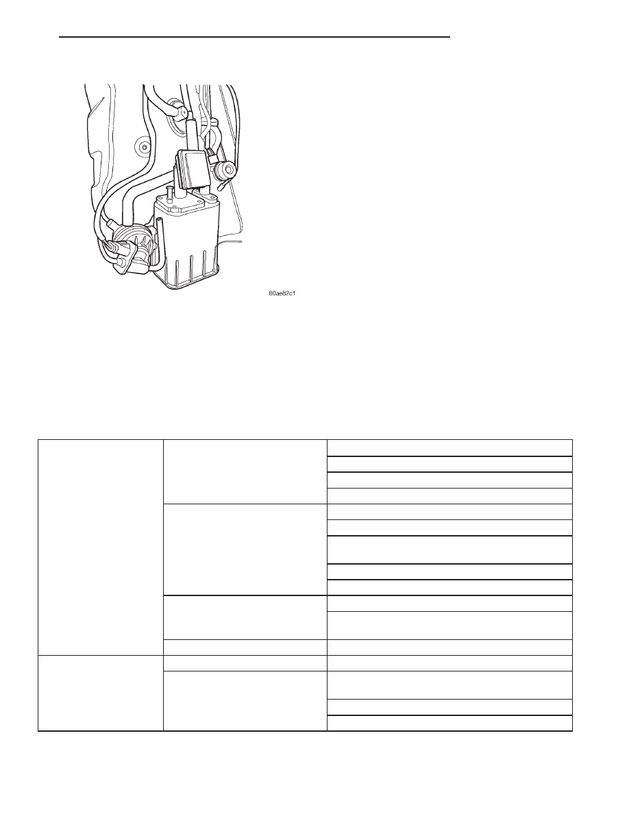
VEHICLE DOES NOT FILL

Fig. 5 ORVR System

Pre-Mature Nozzle
Shut-Off.

Defective fuel tank assembly
components.

Fill tube improperly installed (sump).

Fill tube hose pinched.

Check valve stuck shut.

Control valve stuck shut.

Defective vapor/vent
components.

Vent line from control valve to canister pinched

Vent line from canister to vent filter pinched.

Canister vent valve failure (Requires double
failure, plugged to LDP and atmosphere).

Leak detection pump failed closed.

Leak detection pump filter plugged.

On-Board diagnostics
evaporative system leak test
just conducted.

Canister vent valve vent plugged to atmosphere.

Engine still running when attempting to fill
(System designed not to fill).

Defective fill nozzle.

Fuel Spits Out Of Filler
Tube.

During fill.

See Pre-Mature Shut-Off

At conclusion of fill.

Defective fuel handling component. (Check valve
stuck open).

Defective vapor/vent handling component

Defective fill nozzle

JX

FUEL SYSTEM

14 - 7

DESCRIPTION AND OPERATION (Continued)

SERVICE PROCEDURES

FUEL SYSTEM PRESSURE RELEASE
PROCEDURE

(1) Remove Fuel Pump relay from Power Distribu-

tion Center (PDC). For location of relay, refer to label
on underside of PDC cover.

(2) Start and run engine until it stalls.
(3) Attempt restarting engine until it will no

longer run.

(4) Turn ignition key to OFF position.

CAUTION: Steps 1, 2, 3 and 4 must be performed to
relieve high pressure fuel from within fuel rail. Do
not attempt to use following steps to relieve this
pressure as excessive fuel will be forced into a cyl-
inder chamber.

(5) Place a rag or towel below fuel line quick-con-

nect fitting at fuel rail.

(6) Return fuel pump relay to PDC.
(7) One or more Diagnostic Trouble Codes (DTC’s)

may have been stored in PCM memory due to fuel
pump relay removal. The DRB III

t scan tool must be

used to erase a DTC.

FUEL TANK DRAINING

(1) Remove fuel cap slowly to release tank pres-

sure.

(2) With vehicle on a hoist, drain fuel from tank.
(3) Position a fuel approved container, with a

capacity of at least 16 gallons, under the drain plug
located on the bottom left edge of the tank.

CAUTION: Use

a

Back-Up

wrench

on

tank

to

remove drain plug.

(4) Remove drain plug and allow fuel to drain (Fig. 6).

WARNING: DRAIN PLUG MUST BE INSTALLED AT
THIS TIME AS THERE WILL BE 1 TO 2 GALLONS
OF FUEL LEFT IN THE TANK.

(5) When tank is no longer draining, install drain

plug. Tighten plug to 32 in. lbs.

HOSES AND CLAMPS

Inspect all hose connections (clamps and quick con-

nect fittings) for completeness and leaks. Replace
cracked, scuffed, or swelled hoses. Replace hoses that
rub against other vehicle components or show sign of
wear.

Fuel injected vehicles use specially constructed

hoses. When replacing hoses, only use hoses marked
EFM/EFI.

When installing hoses, ensure that they are routed

away from contact with other vehicle components

that could rub against them and cause failure. Avoid
contact with clamps or other components that cause
abrasions or scuffing. Ensure that rubber hoses are
properly routed and avoid heat sources.

The hose clamps have rolled edges to prevent the

clamp from cutting into the hose. Only use clamps
that are original equipment or equivalent. Other
types of clamps may cut into the hoses and cause
high pressure fuel leaks. Tighten hose clamps to 1
N·m (10 in. lbs.) torque.

Inspect all hose connections such as clamps, cou-

plings and fittings to make sure they are secure and
leaks are not present. The component should be
replaced immediately if there is any evidence of deg-
radation that could result in failure.

Never attempt to repair a plastic fuel line/tube.

Replace as necessary.

Avoid contact of any fuel tubes/hoses with other

vehicle components that could cause abrasions or
scuffing. Be sure that the plastic fuel lines/tubes are
properly routed to prevent pinching and to avoid heat
sources.

QUICK-CONNECT FITTINGS

REMOVAL

When disconnecting a quick-connect fitting, the

retainer will remain on the fuel tube nipple.

WARNING: RELEASE FUEL SYSTEM PRESSURE
BEFORE DISCONNECTING A QUICK-CONNECT FIT-
TINGS. REFER TO THE FUEL PRESSURE RELEASE
PROCEDURE.

(1) Perform

Fuel

Pressure

Release

Procedure.

Refer to the Fuel Pressure Release Procedure in this
section.

Fig. 6 Fuel Tank Drain Plug

1 – FUEL TANK DRAIN PLUG

14 - 8

FUEL SYSTEM

JX

(2) Disconnect negative cable from battery or aux-

iliary jumper terminal.

(3) Squeeze retainer tabs together and pull fuel

tube/quick-connect fitting assembly off of fuel tube
nipple. The retainer will remain on fuel tube.

INSTALLATION

CAUTION: Never

install

a

quick-connect

fitting

without the retainer being either on the fuel tube or
already in the quick-connect fitting. In either case,
ensure the retainer locks securely into the quick-
connect fitting by firmly pulling on fuel tube and fit-
ting to ensure it is secured.

(1) Using a clean lint free cloth, clean the fuel tube

nipple and retainer.

(2) Prior to connecting the fitting to the fuel tube,

coat the fuel tube nipple with clean 30 weight engine
oil.

(3) Push the quick-connect fitting over the fuel

tube until the retainer seats and a click is heard.

(4) The plastic quick-connect fitting has windows

in the sides of the casing. When the fitting com-
pletely attaches to the fuel tube, the retainer locking
ears and the fuel tube shoulder are visible in the
windows. If they are not visible, the retainer was not
properly installed (Fig. 7). Do not rely upon the
audible click to confirm a secure connection.

(5) Connect negative cable to battery or auxiliary

jumper terminal.

CAUTION: When using the ASD Fuel System Test,
the Auto Shutdown (ASD) Relay remains energized
for several minutes, until the test is stopped, or
until the ignition switch is turned to the Off posi-
tion.

(6) Use the DRB scan tool ASD Fuel System Test

to pressurize the fuel system. Check for leaks.

TWO-TAB TYPE FITTING

This type of fitting is equipped with tabs located on

both sides of the fitting (Fig. 8). These tabs are sup-
plied for disconnecting the quick-connect fitting from
component being serviced.

CAUTION: The interior components (O-rings, spac-
ers) of this type of quick-connect fitting are not ser-
viced separately, but new plastic retainers are
available. Do not attempt to repair damaged fittings
or fuel lines/tubes. If repair is necessary, replace
the complete fuel tube assembly.

WARNING: THE FUEL SYSTEM IS UNDER A CON-
STANT PRESSURE (EVEN WITH THE ENGINE OFF).
BEFORE SERVICING ANY FUEL SYSTEM HOSES,
FITTINGS OR LINES, THE FUEL SYSTEM PRES-
SURE MUST BE RELEASED. REFER TO THE FUEL
PRESSURE

RELEASE

PROCEDURE

IN

THIS

GROUP.

DISCONNECTION/CONNECTION

(1) Perform fuel pressure release procedure. Refer

to Fuel Pressure Release Procedure in this group.

(2) Disconnect negative battery cable from battery

or auxiliary jumper terminal.

(3) Clean fitting of any foreign material before dis-

assembly.

(4) To disconnect quick-connect fitting, squeeze

plastic retainer tabs (Fig. 8) against sides of quick-
connect fitting with your fingers. Tool use is not
required

for

removal

and

may

damage

plastic

Fig. 7 Plastic Quick-Connect Fitting/Fuel Tube

Connection

1 – WINDOW
2 – TAB (2)
3 – EAR
4 – SHOULDER (ON TUBE)

Fig. 8 Typical Two-Tab Type Quick-Connect Fitting

1 – TAB(S)
2 – QUICK-CONNECT FITTING

JX

FUEL SYSTEM

14 - 9

SERVICE PROCEDURES (Continued)

retainer. Pull fitting from fuel system component
being serviced. The plastic retainer will remain on
component being serviced after fitting is discon-
nected. The O-rings and spacer will remain in quick-
connect fitting connector body.

(5) Inspect quick-connect fitting body and compo-

nent for damage. Replace as necessary.

CAUTION: When the quick-connect fitting was dis-
connected, the plastic retainer will remain on the
component being serviced. If this retainer must be
removed, very carefully release the retainer from
the component with two small screwdrivers. After
removal, inspect the retainer for cracks or any dam-
age.

(6) Prior to connecting quick-connect fitting to

component being serviced, check condition of fitting
and component. Clean parts with a lint-free cloth.
Lubricate with clean engine oil.

(7) Insert quick-connect fitting to component being

serviced and into plastic retainer. When a connection
is made, a click will be heard.

(8) Verify a locked condition by firmly pulling on

fuel tube and fitting (15-30 lbs.).

(9) Connect negative cable to battery or auxiliary

jumper terminal.

(10) Use the DRB scan tool ASD Fuel System Test

to pressurize the fuel system. Check for leaks.

PLASTIC RETAINER RING TYPE FITTING

This type of fitting can be identified by the use of a

full-round plastic retainer ring (Fig. 9) usually black
in color.

CAUTION: The interior components (O-rings, spac-
ers, retainers) of this type of quick-connect fitting
are not serviced separately. Do not attempt to repair
damaged fittings or fuel lines/tubes. If repair is nec-
essary, replace the complete fuel tube assembly.

WARNING: THE FUEL SYSTEM IS UNDER A CON-
STANT PRESSURE (EVEN WITH THE ENGINE OFF).
BEFORE SERVICING ANY FUEL SYSTEM HOSES,
FITTINGS OR LINES, THE FUEL SYSTEM PRES-
SURE MUST BE RELEASED. REFER TO THE FUEL
SYSTEM PRESSURE RELEASE PROCEDURE IN
THIS GROUP.

DISCONNECTION/CONNECTION

(1) Perform fuel pressure release procedure. Refer

to Fuel Pressure Release Procedure in this section.

(2) Disconnect negative battery cable from battery

or auxiliary jumper terminal.

(3) Clean fitting of any foreign material before dis-

assembly.

(4) To release fuel system component from quick-

connect fitting, firmly push fitting towards compo-
nent being serviced while firmly pushing plastic
retainer ring into fitting (Fig. 9). With plastic ring
depressed, pull fitting from component. The plastic
retainer ring must be pressed squarely into fit-
ting body. If this retainer is cocked during
removal, it may be difficult to disconnect fit-
ting. Use an open-end wrench on shoulder of
plastic retainer ring to aid in disconnection.

(5) After disconnection, plastic retainer ring will

remain with quick-connect fitting connector body.

(6) Inspect fitting connector body, plastic retainer

ring and fuel system component for damage. Replace
as necessary.

(7) Prior to connecting quick-connect fitting to

component being serviced, check condition of fitting
and component. Clean parts with a lint-free cloth.
Lubricate with clean engine oil.

(8) Insert quick-connect fitting into component

being serviced until a click is felt.

(9) Verify a locked condition by firmly pulling on

fuel tube and fitting (15-30 lbs.).

Fig. 9 Plastic Retainer Ring Type Fitting

1 – FUEL TUBE
2 – QUICK CONNECT FITTING
3 – PUSH
4 – PLASTIC RETAINER
5 – PUSH
6 – PUSH
7 – PUSH
8 – PUSH

14 - 10

FUEL SYSTEM

JX

SERVICE PROCEDURES (Continued)


Content   ..  10  11  12  13   ..