Chrysler Stratus Convertible. Manual - part 11


  Index      Chrysler     Chrysler Stratus Convertible - service repair manual 1995-2000 year


Search            


Content   ..  9  10  11  12   ..


Chrysler Stratus Convertible. Manual - part 11


(Methyl Tertiary Butyl Ether) and ETBE (Ethyl Ter-
tiary Butyl Ether). Oxygenates are required in some
areas of the country during winter months to reduce
carbon monoxide emissions. The type and amount of
oxygenate used in the blend is important.

The following are generally used in gasoline

blends:

Ethanol - (Ethyl or Grain Alcohol) properly

blended, is used as a mixture of 10 percent ethanol
and 90 percent gasoline. Gasoline blended with etha-
nol may be used in your vehicle.

MTBE/ETBE - Gasoline and MTBE (Methyl Ter-

tiary Butyl Ether) blends are a mixture of unleaded
gasoline and up to 15 percent MTBE. Gasoline and
ETBE (Ethyl Tertiary Butyl Ether) are blends of gas-
oline and up to 17 percent ETBE. Gasoline blended
with MTBE or ETBE may be used in your vehicle.

Methanol - Methanol (Methyl or Wood Alcohol) is

used in a variety of concentrations blended with
unleaded gasoline. You may encounter fuels contain-
ing 3 percent or more methanol along with other
alcohols called cosolvents.

DO

NOT

USE

GASOLINE

CONTAINING

METHANOL.

Use of methanol/gasoline blends may result in

starting and driveability problems and damage criti-
cal fuel system components.

Problems that are the result of using methanol/

gasoline blends are not the responsibility of Chrysler
Corporation and may not be covered by the vehicle
warranty.

Reformulated Gasoline
Many areas of the country are requiring the use of

cleaner-burning fuel referred to as Reformulated
Gasoline
.

Reformulated

gasoline

are

specially

blended to reduce vehicle emissions and improve air
quality.

Chrysler Corporation strongly supports the use of

reformulated gasoline whenever available. Although
your vehicle was designed to provide optimum perfor-
mance and lowest emissions operating on high qual-
ity unleaded gasoline, it will perform equally well
and produce even lower emissions when operating on
reformulated gasoline.

Materials Added to Fuel
Indiscriminate use of fuel system cleaning agents

should be avoided. Many of these materials intended
for gum and varnish removal may contain active sol-
vents of similar ingredients that can be harmful to
fuel system gasket and diaphragm materials.

FUEL DELIVERY SYSTEM

DESCRIPTION

The front wheel drive car uses a plastic fuel tank

located rear center of the vehicle.

The in-tank fuel pump module contains the fuel

pump and pressure regulator. The pump is serviced
as part of the fuel pump module. Refer to Fuel Pump
Module.

The fuel delivery system consists of:
• the fuel pump module containing the electric

fuel pump, fuel filter/fuel pressure regulator, fuel
gauge sending unit (fuel level sensor) and a separate
fuel filter located at bottom of pump module

• Fuel tubes/lines/hoses

• Quick-connect fittings

• Fuel injector rail

• Fuel injectors

• Fuel tank

• Fuel tank filler/vent tube assembly

• Fuel tank filler tube cap
The fuel delivery system contains a replaceable in-

line filter. The filter attaches to the frame above the
rear of the fuel tank.

OPERATION

A returnless fuel system is used on all vehicles.

Fuel is returned through the fuel pump module and
back to the fuel tank. A separate fuel return line
from the tank to the engine is no longer used.

Relieve fuel system pressure before servicing fuel

system components. Refer to the Fuel System Pres-
sure Release Procedure and follow all Cautions and
Warnings. Most fuel system components attach to the
fuel lines with quick connect fittings. Refer to Quick
Connect Fittings in this section.
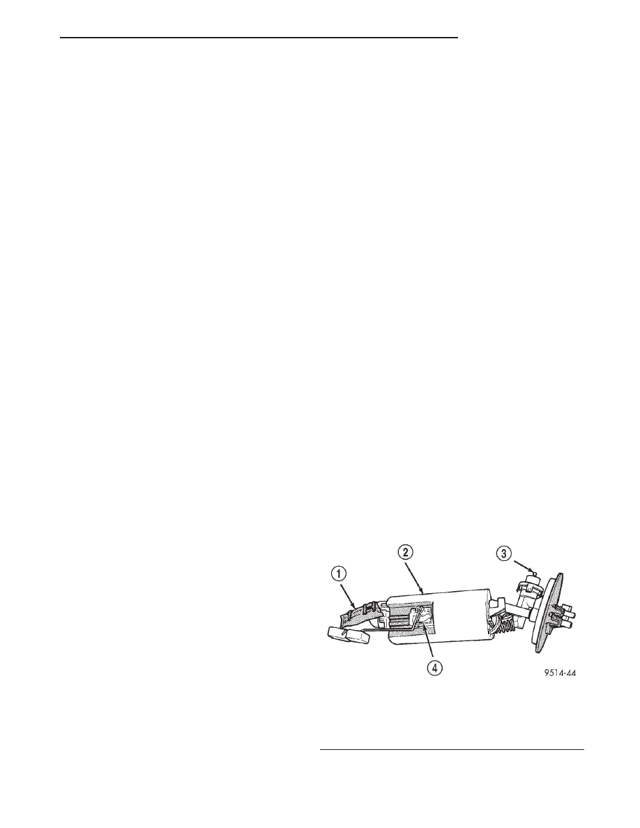
FUEL PUMP MODULE

DESCRIPTION

The fuel pump module is installed in the top of the

fuel tank (Fig. 1).

The fuel pump module contains the following:

Fig. 1 Fuel Pump Module

1 – INLET STRAINER
2 – FUEL RESERVOIR
3 – FUEL PRESSURE REGULATOR
4 – FUEL LEVEL SENSOR

JX

FUEL SYSTEM

14 - 3

DESCRIPTION AND OPERATION (Continued)

• Electric fuel pump

• Fuel pump reservoir

• Inlet strainer

• Fuel pressure regulator

• Fuel gauge sending unit

• Fuel supply line connection
The inlet strainer, fuel pressure regulator

and fuel level sensor are the only serviceable
items. If the fuel pump or electrical wiring har-
ness requires service, replace the fuel pump
module.

The electric fuel pump is located in and is part of

the fuel pump module. It is a positive displacement,
gerotor type, immersible pump with a permanent
magnet electric motor.

OPERATION

The pump draws fuel through a strainer and

pushes it through the motor to the outlet. The pump
contains one check valve. The check valve, in the
pump outlet, maintains pump pressure during engine
off conditions. The fuel pump relay provides voltage
to the fuel pump.

The fuel pump has a maximum deadheaded pres-

sure output of approximately 635 kPa (95 psi). The
regulator adjusts fuel system pressure to approxi-
mately 338 kPa (49 psi).

FUEL PUMP ELECTRICAL CONTROL

Voltage to operate the electric pump is supplied

through the fuel pump relay. For an electrical opera-
tional description of the fuel pump refer to fuel Pump
Relay—PCM Output.

ELECTRICAL PUMP REPLACEMENT

The electric fuel pump is not serviceable. If the

fuel pump or electrical wiring harness needs replace-
ment, the complete fuel pump module must be
replaced. Perform the Fuel System Pressure Release
procedure before servicing the fuel pump.

FUEL LEVEL SENSOR

DESCRIPTION

The level sensor is attached to the side of the fuel

pump module. The level sensor consists of a float, an
arm, and a variable resistor.

OPERATION

As the fuel level increases, the float and arm move

up. This decreases the sending unit resistance, caus-
ing the fuel gauge on the instrument panel to read
full. The fuel level sensor (fuel gauge sending unit)
sends a signal to the PCM to indicate fuel level. The
purpose of this feature is to prevent a false setting of
misfire and fuel system monitor trouble codes if the

fuel level is less than approximately 15 percent of its
rated capacity. It is also used to send a signal for fuel
gauge operation via the PCI bus circuits.

FUEL TANK

DESCRIPTION

The fuel tank is constructed of a plastic material.

Its main functions are for fuel storage and for place-
ment of the fuel pump module. The tank is made
from High density Polyethylene (HDPE) material.

OPERATION

All models pass a full 360 degree rollover test

without fuel leakage. To accomplish this, fuel and
vapor flow controls are required for all fuel tank con-
nections.

All models are equipped with either one or two

rollover valves mounted into the top of the fuel tank
(or pump module).

An evaporation control system is connected to the

rollover valve(s) to reduce emissions of fuel vapors
into the atmosphere. When fuel evaporates from the
fuel tank, vapors pass through vent hoses or tubes to
a charcoal canister where they are temporarily held.
When the engine is running, the vapors are drawn
into the intake manifold. Certain models are also
equipped with a self-diagnosing system using a Leak
Detection Pump (LDP). Refer to the Emission Control
System for additional information.

FUEL INJECTORS

DESCRIPTION

The injectors are positioned in the intake manifold

with the nozzle ends directly above the intake valve
port (Fig. 2).

OPERATION

The fuel injectors are electrical solenoids (Fig. 3).

The injector contains a pintle that closes off an ori-
fice at the nozzle end. When electric current is sup-
plied to the injector, the armature and needle move a
short distance against a spring, allowing fuel to flow
out the orifice. Because the fuel is under high pres-
sure, a fine spray is developed in the shape of a hol-
low cone. The spraying action atomizes the fuel,
adding it to the air entering the combustion chamber.
Fuel

injectors

are

not

interchangeable

between

engines.

FUEL PRESSURE REGULATOR

OPERATION

The fuel system uses a nonadjustable pressure reg-

ulator

that

maintains

fuel

system

pressure

at

14 - 4

FUEL SYSTEM

JX

DESCRIPTION AND OPERATION (Continued)

approximately 338 kPa (49 psi). The fuel pressure
regulator contains a diaphragm, calibrated spring
and a fuel return valve. The spring pushes down on
the diaphragm and closes off the fuel return port.
System fuel pressure reflects the amount of fuel pres-
sure required to open the return port.

The pressure regulator is a mechanical device that

is NOT controlled by the PCM or engine vacuum.

PRESSURE-VACUUM FILLER CAP

OPERATION

The loss of any fuel or vapor out of the filler tube

neck is prevented by the use of a safety filler cap.
The cap releases only under significant pressure 17
kPa (2.5 psi). The vacuum release for all gas caps is
between 2.0 and 3.0 kPa (.29 and.43 psi). The cap
must be replaced by a similar unit in order for the
system to remain effective.

WARNING: REMOVE FUEL FILLER TUBE CAP TO
RELIEVE TANK PRESSURE BEFORE REMOVING
OR REPAIRING FUEL SYSTEM COMPONENTS.

NOTE: THE

MALFUNCTION

INDICATOR

LAMP

COULD BE TURNED ON IF THE FUEL FILLER CAP
IS LOOSE OR MISSING.

ONBOARD REFUELING VAPOR RECOVERY
(ORVR)

DESCRIPTION

ORVR System Schematic and components.

OPERATION

The emission control principle used in the ORVR

system is that the fuel flowing into the filler tube
(appx. 1” I. D.) creates an aspiration effect which
draws air into the fill tube (Fig. 4). During refueling,
the fuel tank is vented to the vapor canister to cap-
ture escaping vapors. With air flowing into the filler
tube, there are no fuel vapors escaping to the atmo-
sphere. Once the refueling vapors are captured by
the canister, the vehicle’s computer controlled purge
system draws vapor out of the canister for the engine
to burn. The vapors flow is metered by the purge
solenoid so that there is no or minimal impact on
driveability or tailpipe emissions.

As fuel starts to flow through the fill tube, it opens

the normally closed check valve and enters the fuel
tank. Vapor or air is expelled from the tank through
the control valve to the vapor canister. Vapor is
absorbed in the canister until vapor flow in the lines
stops, either following shut-off or by having the fuel
level in the tank rise high enough to close the control
valve. The control valve contains a float that rises to
seal the large diameter vent path to the canister. At
this point in the fueling of the vehicle, the tank pres-
sure increase, the check valve closes (preventing tank
fuel from spiting back at the operator), and fuel then
rises up the filler tube to shut-off the dispensing nozzle.

Fig. 2 Fuel Injector Location—Typical

1 – FUEL RAIL
2 – INTAKE MANIFOLD
3 – FUEL INJECTORS

Fig. 3 Fuel Injector

1 – FUEL INJECTOR
2 – NOZZLE
3 – TOP (FUEL ENTRY)

JX

FUEL SYSTEM

14 - 5

DESCRIPTION AND OPERATION (Continued)

If the engine is shut-off while the On-Board diag-

nostics test is running, low level tank pressure can
be trapped in the fuel tank and fuel can not be added
to the tank until the pressure is relieved. This is due
to the leak detection pump closing the vapor outlet
from the top of the tank and the one-way check valve
not allowing the tank to vent through the fill tube to
atmosphere. Therefore, when fuel is added, it will
back-up in the fill tube and shut off the dispensing
nozzle. The pressure can be eliminated in two ways:
1. Vehicle purge must be activated and for a long
enough period to eliminate the pressure. 2. Removing
the fuel cap and allowing enough time for the system
to vent thru the recirulation tube.

CONTROL VALVE

DESCRIPTION

It is a valve in the top of the fuel tank that con-

trols fuel fill rate and fuel fill level and directs
vapors to a storage area.

OPERATION

The valve controls the fuel fill rate and set the fuel

level in the fuel tank. It also allows the proper oper-
ation of OBDII leak detection monitor. It prevent liq-
uid fuel carry over into the EVAP system (Fig. 5).

ROLLOVER VALVES

DESCRIPTION

All vehicles have rollover valve(s) on top of the fuel

tank.

Fig. 4 ORVR System Schematic

1 – FUEL CAP
2 – RECIRCULATION TUBE
3 – LIQUID SEPARATOR
4 – PURGE
5 – W/LDP
6 – BREATHER ELEMENT

7 – W/O LDP
8 – CANISTER
9 – ROLLOVER VALVE
10 – FUEL TANK
11 – CHECK VALVE
12 – CONTROL VALVE

14 - 6

FUEL SYSTEM

JX

DESCRIPTION AND OPERATION (Continued)


Content   ..  9  10  11  12   ..