Chery QQ6 (SQR473F Engine-Mechanical). Service Manual - part 3


  Index      Chery     Chery QQ6 (SQR473F Engine-Mechanical). Service Manual


Search            copyright infringement  


Content      ..     1      2      3      4      ..


Chery QQ6 (SQR473F Engine-Mechanical). Service Manual - part 3


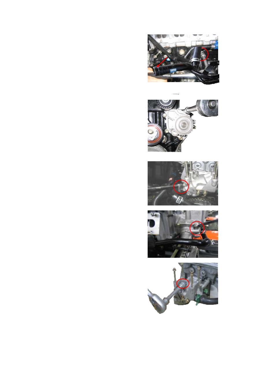
5.3  Use  a  10mm  sleeve  to  remove  the  fixing  bolt  of 

discharging  tube  of  water  pump  and  then  pull  out  the 

discharging tube. 

Note:  in  case  the  O-ring  on  discharging  tube  of  water 

pump is loose, broken or aging, be sure to replace. 


5.4  Use  a  10mm  sleeve  to  remove  the  fixing  bolt  of 

water pump and then take out the water pump assembly; 

when removing, be careful not to damage cushion of the 

water  pump,  if  damaged,  replace  with  a  new  one.  The 

water pump can not be decomposed to maintain. 

5.5 Check water seal of the water pump for water leak; if 

water  pump  bearing  is  loose,  replace  the  assembly. 

Follow  the  order  adverse  to  that  for  disassembly  of  the 

water pump to install it. 


5.6 Disassembly and installation of thermostat 

5.7  Use  a  caliper  to  take  off  the  clamps  on  the  two 

discharging tubes and then pull out the rubber hoses. 


5.8  Use  a  10mm  sleeve  to  remove  the  fixing  bolt  of 

thermostat cover and then take out the thermostat. 


5.9 Use a 10mm socket wrench to remove the thermostat 

seat. Be careful not to damage the thin sheet gasket. 


-------------------------------------------------------------------------------------------------------------------------------------------------------------

6. Inspection of thermostat: 

(1)  Under  normal  temperature,  inspect  seating  status  of 

the valve and it should tightly seat. 

(2)  Inspect opening temperature and maximum stroke of 

the valve. 

Opening temperature of the valve is 87±2℃ 

Maximum stroke of the valve is 8mm 

Full opening temperature of the valve is 104℃ 

(3)  Then  check  if  the  valve  closes  at  the  temperature 

5

  lower  than  the  opening  t

emperature.  If  not 

compliant,  replacement  with  a  new  thermostat  is 

required.  Follow  the  order  adverse  to  that  for 

disassembly  of  the  thermostat  to  install  it.  When 

installing,  check  if  the  gasket  of  the  thermostat  is 

damaged,  if  thermostat  seat  and  thermostat  cover 

casing  plane  are  satisfactory.  Check  the  sealing 

gasket  for  damage,  if  damaged,  replace  with  new 

sealing element. 

7. Disassembly of A/C pipeline 

See  Disassembly  of  A/C  Compressor  for  disassembly 

of A/C pipeline. 

8. Disassembly of power-assisted steering pipeline. 

See Disassembly of Power-assisted Steering Oil Pump 

for disassembly of power-assisted steering pipeline. 

9. Disassembly of intake and exhaust manifold. 


9.1  Use  a  10#  sleeve  to  remove  the  fixing  bolt  of  air 

intake pipe. 


9.2  Use  a  cross-head  screwdriver  to  loosen  the  clamp 

connecting intake hose and electronic throttle body. 


-------------------------------------------------------------------------------------------------------------------------------------------------------------

9.3  Use  a  13#  sleeve  to  remove  the  connecting  bolt  of 

three-way  catalytic  converter  and  exhaust  intermediate 

pipe. 

Torque: 60±5 Nm. 


9.4 Use a 10# sleeve to remove heat insulating  mattress 

of exhaust pipe. 


9.5  Use  a  13#  sleeve  to  remove  the  connecting  bolt  of 

exhaust manifold and three-way catalytic converter. 

Torque: 60±5 Nm. 


9.6 Use a 13# sleeve to remove the fixing bolt of exhaust 

manifold. 


10. Disassembly of connecting portion of transmission 

case. 

10.1  Use  pliers  to  remove  the  fixing  steel  wire  clip  of 

gearshift control cable. 


-------------------------------------------------------------------------------------------------------------------------------------------------------------

10.2  Use  pliers  to  remove  the  fixing  clip  of  gearshift 

control  cable  outer  case  and  then  take  off  the  gearshift 

control cable. 


10.3  Use  a  13#  sleeve  to  loosen  the  adjusting  screw  of 

clutch  control  cable  and  then  take  off  the  clutch  control 

cable. 


10.4 Use a 13# sleeve to loosen the fixing bolt of clutch 

control cable on the transmission case. 


10.5  Use  a  17#  wrench  to  loosen  the  bleeding  bolt  of 

transmission case to discharge the gear oil. 

10.6  See  Service  Manual  for  Chassis  for  disassembly 

of suspension travel portion. 

10.7 Use a crow to pry out the half shaft. 

11. Disassembly of suspension portion 


11.1 Use a 13# sleeve to remove the fixing bolt  for rear 

engine mount bracket of transmission case. 

Torque: 60±5Nm. 


-------------------------------------------------------------------------------------------------------------------------------------------------------------

11.2 Use a 18# sleeve to loosen the fixing bolt  for front 

engine mount bracket. 

Torque: 80±5 Nm. 


11.3 Use a crane to  hoist the engine  until the iron  chain 

just bears tensile force. 


11.4 Use a 15# sleeve to  loosen the  fixing bolt  for right 

engine mount bracket. (at rear of transmission) 

Torque: 100±5 Nm. 


11.5  Use  a  13#  sleeve  to  loosen  the  three  connecting 

bolts for right engine mount bracket. 

Torque: 65±5Nm. 


11.6  Use  a  13#  sleeve  to  loosen  the  three  connecting 

bolts for left engine mount bracket. 

11.7 Pull out oil pipe connector and junctions of relevant 

pipelines. Make sure that relevant junction parts have all 

detached. 

11.8 Hoist the engine up. 


-------------------------------------------------------------------------------------------------------------------------------------------------------------

12. Separation of transmission case assembly and engine 

12.1  Use  a  10#  sleeve  to  remove  the  gearshift  control 

cable bracket on the transmission case. 


12.2 Use a 13# sleeve to loosen the four fixing bolts for 

front engine mount bracket. 

Torque: 65±5Nm. 


12.3  Use  a  13#  sleeve  to  remove  the  connecting  bolt  of 

transmission case and  engine, and then  make the engine 

and the transmission separate. 

Torque: 100±10 Nm. 


-------------------------------------------------------------------------------------------------------------------------------------------------------------


II. Installation Procedure 

1.  Please follow the order adverse to that for disassembly to install, but care should be taken for 

the following matters. 

(1)  When  hoisting,  do  not  install  exhaust  manifold  first,  because  the  longitudinal  separation  of 

engine compartment is not big enough; otherwise, it may affect the assembly. 

(2) After installation, please adjust the stroke of clutch pedal. When adjusting, adjust it to a proper 

position according to the corresponding requirements, in case of a too big free stroke of clutch, it 

may make sound when shifting gear or fail to release; while in case of a too small stroke, wear of 

friction plate may be accelerated and travel weakness may occur, if severely, the friction plate may 

be burnt out.   


Chapter Ten Disassembly of Intake Manifold 

I. Disassembly Procedure 

1.  Use  an  8#  sleeve  to  remove  the  four  fixing  bolts  of 

ignition  coil  and  then  remove  such  connections  as 

ignition cable/injection nozzle harness etc. 


2 Use a 10# sleeve to remove the bolt of intake manifold 

fixing bracket. 


-------------------------------------------------------------------------------------------------------------------------------------------------------------

3.  Use  a  10#  sleeve  to  remove  the  fixing  bolt  of 

compressor bracket. 

Torque: 30±3 Nm. 


4  Use  a  10#  sleeve  to  remove  the  fixing  bolt  of  intake 

manifold and then take off the intake manifold assembly. 

Torque: 8+3Nm. 


Chapter Eleven Disassembly of Cylinder Head 

I. Disassembly Procedure 

1  Use  a  10#  sleeve  to  remove  the  fixing  bolt  of 

valve cover. 

Torque: 8±3 Nm. 


2.  Get  the  special  tool  CH-20010  stuck  into  the 

groove on camshaft. 


-------------------------------------------------------------------------------------------------------------------------------------------------------------

3.  Use  a  18#  sleeve  to  loosen  the  fixing  bolt  of 

camshaft timing gear. 

Torque: 120±5Nm. 


Note: 

There  is  no  difference  between  intake 

camshaft and exhaust camshaft, they can be interchanged. 


4. Use a cross-head screwdriver to loosen the fixing 

bolt on inner fender of timing gear and then take out 

the inner fender of timing gear. 


5.  Use  a  10#  sleeve  to  remove  the  fixing  bolt  of 

camshaft  bearing,  take  out  the  camshaft  assembly 

and then the hydraulic tappet system. 

Torque: 9.5±1.5 Nm. 


Note: 

The  positions  of  both  camshaft  bearing  and 

bolts,  including  the  order  of  camshaft  bearing,  are 

unchangeable,  and  should  be  conformity  with  the  marks 

during assembly/disassembly. 


-------------------------------------------------------------------------------------------------------------------------------------------------------------

6.  Use  an  hexagon  torque  wrench  to  loosen  the 

fixing  bolt  of  cylinder  head  and  then  take  off  the 

cylinder head assembly. 

Torque: 50±5 Nm. 


Note: 

Follow  the  order  as  shown  in  the  figure  to 

loosen the fixing bolts of cylinder head. 


7. Disassembly of valve 

7.1  Use  a  special  tool  to  press  down  the  valve 

spring,  take  out  the  locking  plate,  and  then  take  off 

valve spring, valve and valve seat insert. 


7.2 Use a special tool to pull out the valve oil seal. 


-------------------------------------------------------------------------------------------------------------------------------------------------------------


II. Overhaul of Cylinder Head System 

1. Detection of camshaft 

1.1  Measurement  of  height  of  cam.  Use  an  outside 

micrometer to measure wheel height of the cam. 

Wheel height of the intake camshaft: 37.11mm. 

Wheel height of the exhaust camshaft: 37.09mm. 


1.2  Inspection  of  camshaft  journal.  Use  an  outside 

micrometer to measure each journal of the camshaft, 

please see Specification Table for specific data. 


2. Detection of valve 

2.1 Detection of  valve spring.  Two items  of  data of 

valve spring should be measured. 

Length of the spring: 49mm 

Squareness of the spring: 1.2mm (limit) 


2.2. Detection of valve. 

2.2.1 Measurement of diameter of valve stem 


Measurement point 

-------------------------------------------------------------------------------------------------------------------------------------------------------------

2.2.2 Measurement of valve guide inside diameter 

Use  an  inside  micrometer  to  measure  inside 

diameter of the guide. 

Fit  clearance  between  intake  valve  stem  and  valve 

guide: 0.012~0.043mm 

Fit clearance between exhaust valve stem and  valve 

guide: 0.032~0.063mm 

Note: 

If  abnormal  noise  is  generated  due  to 

serious  wear  of  valve  guide,  do  not  replace  the  valve 

guide,  because  the  assembly  technique  requirements  to 

valve guide is very strict; please replace the cylinder head 

assembly. 


2.3 Boring and grinding valve seat insert 

2.3.1 Inspection  of fitting surface  of  valve.  Apply a 

circle of red lead on the valve sealing strip and then 

gently  place  the  strip  onto  the  valve  seat  insert, 

softly and forcibly  press it  down, but  do  not turn  it. 

Take out the valve, observe if there is broken part on 

the  red  lead,  if  any,  boring  and  grinding  the  valve 

seat insert is required. 


2.3.2  Select  an  appropriate  reamer,  use  45°  conical 

surface  as  cooperate  standard  value  to  check  valve 

cooperation  position:  the  optimal  position  is  the 

center  of  the  valve,  if  not  so,  be  sure  to  revise.  Cut 

on  the  conical  surface  70°  inward  and  30°  outward 

at the center of the cooperation position. 


2.3.3  Perform  seat  grinding  for  the  valve  sealing 

strip with polishing compound 


Measurement point 

-------------------------------------------------------------------------------------------------------------------------------------------------------------

2.3.4 Detection of planeness of cylinder head 

Follow  the  method  as  shown  in  the  figure  to 

measure planeness of the cylinder head with a feeler 

gauge;  the  planeness  of  the  cylinder  should  not 

exceed  0.05-0.10mm,  if  exceeding  this  valve, 

replace the cylinder head assembly. 


III. Assembly of Cylinder Head Assembly 

1.  Please  follow  the  order  adverse  to  that  for 

disassembly  of  cylinder  head  to  install,  but  care 

should  be  taken  for  the  following  matters  during 

installation. 

2.  Use  the  special  tool  CH-20012  to  install  new 

valve oil seal onto the guide first. 


3. Insert big end of the guide onto the valve guide. 


4.  Envelope  the  special  tool  onto  CH-20012,  and 

then softly and forcibly compact. 


-------------------------------------------------------------------------------------------------------------------------------------------------------------

5.  Use  a  hammer  to  knock  the  valve  oil  seal 

installation tool, when a metal crash sound is heard, 

take out CH-20012. 


6.  The  methods  for  installation  and  assembly  of 

valve spring are the same. Then install valve, spring, 

keeper,  top  barrel  and  rocker  arm.  (when  installing 

the top barrel, add a little engine oil into the hole). 


7. Install camshaft and camshaft bearing shell cover 

assembly. 


Note: 

When  installing,  remember  to  differentiate  intake 

camshaft  from  exhaust  cam.  The  intake  camshaft  has  a 

gear  at  tail,  and  pay  attention  to  the  diacritical  marks  on 

camshaft bearing shell covers. 


8. Installation of camshaft and oil seal 

8.1 After adding engine  oil  on the camshaft bearing 

shell,  place  intake  and  exhaust  camshafts,  cover 

bearing shell covers properly, install the fixing bolts 

for  the  bearing  shell  covers,  and  then  use  a  10mm 

sleeve to hold down the bearing shell covers step by 

step (the two bolts  on the one and the same bearing 

shell  cover  should  be  tightened  at  the  same  time). 

Torque: 8.5±1.5 Nm.   


9.  Remember  to  apply  sealant  to  the  position  as 

shown in the figure when installing the first bearing 

shell. 

10.  Tightening  order  of  camshaft  bearing  shell 

cover. 

Tighten  the  camshaft  bearing  shell  cover  as  shown 

in the figure. 

Installation of camshaft oil seal: 

Apply  a  little  engine  oil  on  the  camshaft  oil  seal, 


-------------------------------------------------------------------------------------------------------------------------------------------------------------

envelop  the  oil  seal  onto  the  camshaft,  and  then 

install use the special tool. 


11.  Remember  to  check  elasticity  of  valve  cover 

gasket for aging and breakdown, if any, replace with 

new  one.  When  installing,  pay  attention  to 

installation position. 


12. Tighten the valve cover bolt. 


-------------------------------------------------------------------------------------------------------------------------------------------------------------


Chapter Twelve Disassembly and Installation of Oil Pump and 

Lubrication System 

I. Disassembly Procedure 

1. Roll  over the engine and use a 10# sleeve to remove 

the fixing bolt of oil pan. 

Torque: 15+3 Nm 


2. Use a screwdriver to pry  out the  oil  pan at the  given 

position for prying out on the oil pan. 


Note: 

Because  the  oil  pan  and  cylinder  block  are  sealed 

with  glue,  so,  do  not  knock  with  such  hard  articles  as 

hammer etc. when disassembling, use a rubber hammer to 

slowly strike at left and right instead. 


3. Use a 10# sleeve to remove the fixing bolt  of engine 

oil strainer. 


4. Use an 8# sleeve to remove the fixing bolt  of engine 

oil guard board. 


-------------------------------------------------------------------------------------------------------------------------------------------------------------


Content      ..     1      2      3      4      ..