Chery QQ6 (SQR473F Engine-Mechanical). Service Manual - part 2


  Index      Chery     Chery QQ6 (SQR473F Engine-Mechanical). Service Manual


Search            copyright infringement  


Content      ..      1      2      3      ..


Chery QQ6 (SQR473F Engine-Mechanical). Service Manual - part 2


production of this tool to other manufacturer. This tool is of the first modification.   

HAZET-6290-1CT means it is a standard tool produced by HAZET company with its model 

as 6290-1CT. 


II. Special Tools Chart   
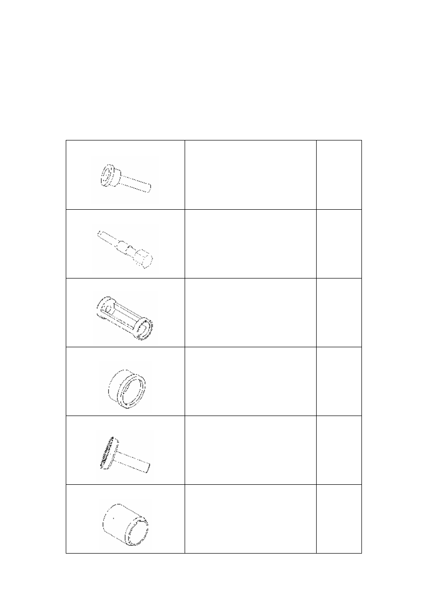
CH-20002 


Installation  tool  for  camshaft  oil  seal: 

used to install camshaft oil seal. 


Same as A5 

CH-20003 


Engine  timing  tool:  used  to  time 

crankshaft. 


Same as A5 

CH-20004 


Adaptor:  used  to  install  and  remove 

valve spring (match  with Eastar special 

tool MLR-MD998772A). 

Same as A5 

CH-20005 


Installation  tool  for  crankshaft  rear  oil 

seal:  used  to  install  crankshaft  rear  oil 

seal. 

Same as A5 


CH-20006 


Installation  handle  for  crankshaft  rear 

oil  seal:  used  to  install  crankshaft  rear 

oil seal. 

Same as A5 


CH-20007 


Installation  sleeve  for  crankshaft  front 

oil  seal:  used  to  install  crankshaft  front 

oil seal. 

Same as A5 


-------------------------------------------------------------------------------------------------------------------------------------------------------------

CH-20008 


Installation  sleeve  for  crankshaft  front 

oil seal 

Same as A5 

CH-20009 


Locating  tool  for  flywheel:  used  to 

locate flywheel. 

Same as A5 


CH-20010 


Camshaft  timing  tool:  used  to  time 

camshaft. 

Same as A5 


CH-20011 


Installation  tool  for  camshaft  oil  seal: 

used to install camshaft oil seal. 

Same as A5 


CH-20012 


Valve  oil  seal  guide  sleeve:  used  to 

install valve oil seal. 

Same as A5 


CH-20013 


Valve  oil  seal  remover:  used  to  remove 

valve oil seal. 

Same as A5 


CH-20015 


Belt  pulley  bolt  remover:  used  to 

remove belt pulley clip. 

Same as A5 

-------------------------------------------------------------------------------------------------------------------------------------------------------------

CH-20017 


Installation  tool  for  valve  keeper:  used 

to install valve keeper. 

Same as A5 

CH-20018-A 


Valve  spring  remover:  used  to  remove 

valve spring. 

Same as A5 


Recommended tools 


Loop wheel machine: used to raise engine. 


Engine  maintenance  workbench:  the  workbench  for 

disassembly and assembly of engine. 


Fuel  pressure  gauge:  used  to  measure  oil  pressure  of 

engine. 

-------------------------------------------------------------------------------------------------------------------------------------------------------------


Pressure  gauge  for  cylinder:  used  to  measure  cylinder 

pressure.  When  measuring,  remove  spark  plug  first, 

screw instrument pipe orifice into the position of spark 

plug,  use starter to drag the  engine to rotate, and then 

fetch  the  maximum  reading  of  the  pressure  gauge  for 

cylinder as cylinder pressure of this cylinder. 


Chapter Four Measurement of Cylinder Pressure 

I. Detection of Cylinder Pressure 

Measurement  of  cylinder  pressure  is  the  major  index  for  judgment  of  engine  working  condition, 

through which, we can definitely judge if a certain system of engine works well. Therefore, during 

maintenance of engine, measurement of cylinder pressure is indispensable. 

1. Measuring process 


1.1 Turn  off ignition switch,  pull  out all ignition cables 

from  spark  plug  side,  and  then  pull  out  harness 

connector of injection nozzle. 


1.2  Use  a  spark  plug  sleeve  to  loosen  the  spark  plug 

whose  cylinder  will  be  measured.  Explanation:  do  not 

remove  the  spark  plug  whose  cylinder  will  not  be 

measured. 


Please  select  a  cylinder  pressure 

gauge  with  accurate  reading  and  let  its 

pointer  return  to  zero;  otherwise,  it  may  affect 

accuracy of reading. 

-------------------------------------------------------------------------------------------------------------------------------------------------------------

1.3  Screw  the  cylinder  pressure  gauge  joint  slowly  and 

vertically  into  the  spark  plug  hole.  Do  not  screw  too 

tightly for fear that it may be difficult to disassemble.   

1.4  Step  down  clutch  pedal,  start  the  engine  and  let  it 

run for about 5-6s, then fetch the numerical value. 


2. Judgment of cylinder pressure value 

2.1 Correct cylinder pressure 

The  standard  cylinder  pressure  value  should  be 

10-13.5bar. With use of engine, this value will fall, but 

it  should  not  be  below  9bar  with  the  pressure 

difference among cylinders not exceeding 3bar. 

2.2  In  case  cylinder  pressure  of  engine  is  below  the 

standard  value,  it  indicates  deficiency  of  cylinder 

pressure,  the  main  cause  of  which  may  be  untight 

piston  ring  seal  or  valve.  Please  further  analyze  and 

check.     


When  starting  the  engine, 

ensure 

adequate 

quantity 

of 

electricity.  Correct  cylinder  pressure  can 

only  be  measured  out  with  revolution  of 

engine as 200-300r/min. 

-------------------------------------------------------------------------------------------------------------------------------------------------------------


Chapter Five Disassembly of Power-assisted Steering System 

I. Disassembly Procedure 

1.  Use  a  snap  ring  pliers  to  loosen  the  clamp  on 

connecting  hose  of  steering  fluid  reservoir  and  steering 

pump. Use a clean container to reclaim the steering fluid. 


2. Use a 21# sleeve to remove the fixing bolt of steering 

pump oil pipe. 

Torque: 20+5Nm. 


3.  Use  a  10#  sleeve  to  loosen  the  (upper)  fixing  bolt  of 

steering pump adjusting bracket. 

Torque: 20+5Nm. 


4.  Use  a  10#  sleeve  to  loosen  the  (lower)  fixing  bolt  of 

steering pump adjusting bracket. 

Torque: 20+5Nm. 


-------------------------------------------------------------------------------------------------------------------------------------------------------------


5.  Use  a  10#  open  end  wrench  to  loosen  the  adjusting 

bolt  of steering  pump bracket, and then pull the steering 

pump upwards to loosen and take off the belt. 


6.  Use  a  10#  sleeve  to  loosen  the  connecting  bolt  of 

steering  pump  and  compressor  bracket,  pull  out  harness 

connector,  and  then  dismount  the  steering  pump 

assembly. 


II. Overhaul 

Steering  pump  can  not  be  repair,  if  such  failure  as  abnormal  noise  or  oil  leak  exists,  replace  the 

assembly. 

III. Installation of the Steering Pump 

1. Follow the order adverse to that of disassembly to install. 

2. After installation of steering oil pump, duly adjust tightness of belt through adjusting bolt. 

3. After power steering pump is  properly installed, refill  with special steering pump oil, and then 

bleed air for the power steering pump after the engine starts. 

4. Air bleeding method: 

4.1 Hoist the vehicle to let its front wheels leave ground. 

4.2 Turn the steering wheel left and right to the ends (duration for each time should not exceed 5s, 

otherwise,  the  power  steering  pump  is  likely  to  be  burnt  out)  until  the  oil  pump  does  not  make 

sound. Note that oil storage kettle should not be lack of steering pump oil. 


Note:  when  dismounting  the 

steering  pump,  please  block  the  oil 

pipe joint with clean cotton cloth. 

-------------------------------------------------------------------------------------------------------------------------------------------------------------


Chapter Six Disassembly of A/C Compressor 

I. Disassembly Procedure 

Before disassembling the compressor, disassemble the steering oil pump first. 

1. Use a 12# sleeve and a universal joint connecting rod to 

loosen  the  connecting  bolt  of  A/C  high  and  low  pressure 

pipelines.  (Note:  if  there  is  R134a  in  the  condenser,  use  a 

special equipment to reclaim first.) 


After 

the 

pipeline 

is 

loosened,  immediately  block  high 

and  low  pressure  holes  of  the  compressor 

with  clean  cotton  cloth  to  avoid  entry  of 

foreign material into the compressor! 


2. Hoist the vehicle and then use a 13# sleeve to loosen the 

fixing bolt of the compressor from underside. 

Torque: 20+5Nm. 


3.  Lower  the  vehicle  and  then  use  a  13#  sleeve  to  loosen 

the  fixing  bolt  of  the  compressor  from  upside.  Use  a  13# 

sleeve  to  loosen  the  fixing  bolt  at  middle  of  the 

compressor, and then dismount the compressor assembly. 

Torque: 20+5Nm. 


-------------------------------------------------------------------------------------------------------------------------------------------------------------


II. Overhaul of Compressor 

Inside of the compressor are assembled with highly machined fine parts, in case abnormal noise or 

internal failure is found, replace the assembly.   

III. Installation procedure 

For the installation order, please refer to the disassembly order, and then follow the order adverse 

to that for disassembly to install. It should be noted that, when installing the A/C pipeline joint on 

the compressor, be sure to replace with a new gasket and tight the joint at specified torque to avoid 

leak. 


Chapter Seven Disassembly of Generator 

I. Disassembly Procedure 


1.  Use  a  10#  sleeve  to  remove  the  connecting  line  of 

battery. 


2. Use a 10# sleeve to  loosen the fixing bolt of  generator 

adjusting bracket, and then take off the adjusting bracket. 

Torque: 30+5Nm. 


Before  disassembling  the 

generator, remove the connecting 

line of battery first. 

-------------------------------------------------------------------------------------------------------------------------------------------------------------

3.  Use  a  13#  sleeve  to  remove  lower  fixing  bolt  of  the 

generator. 

Torque: 40+5Nm. 


4. Use a 10# sleeve to remove the fixing bolt of generator 

anode harness, pull out the harness connector, remove the 

belt and then take out the generator. 


II. Overhaul of Generator 

In  case  the  generator  makes  abnormal  noise  or  its  yield  is  too  high  or  too  low,  replace  the 

assembly. 

III. Installation Procedure 

The installation order of the generator is adverse to that for its disassembly. After the generator is 

installed, adjust deflection of the belt. 


-------------------------------------------------------------------------------------------------------------------------------------------------------------


Chapter Eight Replacement of Engine Timing Belt 

I. Disassembly Procedure 


1. Disassembly of engine timing belt: 

1.1 Follow the disassembly methods for power-assisted steering pump, compressor and generator 

to disassemble the generator and compressor belt.   

1.2  Use  a  5mm  hexagon  wrench  to  remove  the  five 

fixing bolts on timing upper cover. 


1.3 The positions of the five fixing bolts on timing upper 

cover are shown by the red circles in the figure. 


1.4  Use  a  13#  sleeve  to  loosen  the  crankshaft  timing 

adjusting hole bolt. (The adjusting bolt is at upside of the 

starter) 


In order to ensure normal and 

highly  effective  working  of  the 

engine,  replacing  the  timing  belt  at 

50,000km mileage is recommended. 

-------------------------------------------------------------------------------------------------------------------------------------------------------------

1.5 Insert the special tool CH-20003 into the timing hole 

and  tighten,  use  a  wrench  to  turn  the  big  nut  in  the 

crankshaft  pulley  to  make  the  crankshaft  rotate,  at  the 

same  time,  slowly  screw  in  CH-20003  until  the 

crankshaft can not rotate back and forth any longer. 


1.6  Use  a  13#  sleeve  to  remove  the  six  fixing  bolts  of 

crankshaft pulley and take out the crankshaft pulley. 

Torque: 55+5 Nm. 


1.7  Use  a  10#  sleeve  to  remove  the  six  fixing  bolts  on 

timing lower cover. 


1.8 The  positions  of the six fixing bolts  on timing  lower 

cover are shown by the red circles in the figure. 


1.9  It  should  be  specially  explained  that,  the  position  of 

the  fixing  bolt  at  left  upside  on  the  lower  cover  is  very 

occult,  for  removal  of  which,  use  of  universal  joint 

connecting  rod  is  required.  Alternatively,  use  a  13mm 

sleeve to remove the three bolts of suspension bracket to 

take off the suspension bracket. 


-------------------------------------------------------------------------------------------------------------------------------------------------------------

1.10  Use  a  10#  sleeve  to  loosen  the  fixing  bolt  of  the 

tension pulley to take off the timing belt. 

Torque: 27±3 Nm. 


Note:   

when  taking  off  the  timing  belt,  pay 

attention  to  running  direction  of  the  belt 

and refer to running direction of the engine 

crankshaft  and  the  arrowhead  direction  on 

the belt. 


II. Installation of Timing Belt 

1.  Loosen the fixing bolt of tension pulley and turn the 

tension pulley to minimum tension position. 

2.  Install the belt. 

3.  Use  a  5mm  hexagon  wrench  to  turn  the  tension 

pulley,  when  it  turns  to  a  position  that  the  hexagon 

wrench  and  the  fixing  bolt  are  roughly  on  the  same 

horizontal line, stop and tighten the fixing bolt. 

4.  Install timing lower cover. 

5.  Install crankshaft pulley. 

6.  Install  relevant  accessories  and  check  deflection  of 

the belt. 

7.  Install timing upper cover. 

8.  The installed timing belt is as shown in the figure. 


Note: 

During  the  disassembly  process,  be 

sure  not  to  turn  crankshaft/camshaft; 

otherwise,  ignition  timing  will  need 

re-check. 


-------------------------------------------------------------------------------------------------------------------------------------------------------------


III. Adjustment of Timing (general overhaul) 

1. Turn the crankshaft to  make the  four  pistons align  on  a horizontal line in the cylinders, screw 

the special tool into the crankshaft timing adjusting  hole  at left rear of the cylinder (last segment 

of  the  crankshaft),  and  then  make  the  crankshaft  unable  to  turn  left  and  right  (the  bolt  of  the 

special tool must enter into the screw hole plane of the cylinder). 

2. After intake and exhaust camshaft is installed properly, install the camshaft timing gear, turn the 

groove  at  tail  of  intake  and  exhaust  camshaft  to  horizontal  direction,  and  then  insert  the  special 

tool into the groove and fix.   

3. After crankshaft and camshaft have been fixed according to requirements, install timing belt. In 

order to  facilitate  installation  of timing belt, temporarily  do  not tighten the bolt fixing the timing 

gear onto  camshaft and let  it rotate freely, then  fix the timing  gear bolt after the  tensioner  pulley 

has fastened the timing belt to the specified value. After that, install other parts. 

IV. Adjustment of Timing (minor overhaul) 

Replace valve spring, grind valve and replace camshaft (do not raise the engine). 

1.  Remove the valve cover. 

2.  Remove the timing gear cover. Turn the timing gear. 

3.  Let  the  groove  at  tail  of  intake  and  exhaust  camshaft  on  a  horizontal  line,  then  insert  the 

projecting portion of the special tool into the groove and fix. 

4.  Turn the crankshaft, screw the special tool into the crankshaft timing adjusting hole at left rear 

of the  cylinder (last segment  of the crankshaft), and then  make the crankshaft  unable to turn 

left  and  right  (if  the  cylinder  head  is  removed,  it  can  be  found  that  the  pistons  of  the  four 

cylinders now align at a horizontal position).   

5.  Install timing belt and make tightness of the belt conform to requirements. 

6.  Fasten the fixing bolt of timing gear. 

7.  Install other accessories, such as timing cover and belt pulley etc. 


Special tool for camshaft timing check      Special tool for crankshaft timing check 


        (CH-20010)   


(CH-20003) 

-------------------------------------------------------------------------------------------------------------------------------------------------------------


Chapter Nine Disassembly of Engine Assembly 

I. Disassembly Procedure 


1. Disassembly of engine wire harness 

1.1 Pull out the connecting plug of engine wire harness. 


1.2 Use a 10# sleeve to loosen the fixing bolt  of  engine 

ground. 


2. Use a 10# sleeve to remove the fixing bolt and bearer 

of battery. 


Note: 

Please  use  regular  equipment,  especially  for  such 

equipment as crane etc., so as to avoid occurrence of accident. 

Before  any  disassembly  job,  disassemble  cathode  of  battery 

first, so as to protect safety of electricity consumption equipment. 

When  disassembling  engine  suspension,  pay  attention  to 

disassembly order, so as to avoid occurrence of accident. 

-------------------------------------------------------------------------------------------------------------------------------------------------------------

3. Use a 13# sleeve to remove the bolt of battery support 

fixed mount. 


4. Disassembly of cooling system. 

4.1  Hoist  the  vehicle,  place  away  a  coolant  collector, 

unscrew  bleeder  bolt  of  the  water  tank  to  discharge  the 

coolant. 


4.2  Use  the  snap  ring  pliers  to  loosen  the  clamp  on 

connecting pipe of water tank. 


4.3  Use  the  snap  ring  pliers  to  loosen  the  connecting 

water pipe of A/C heating water tank. 


4.4  Use  the  snap  ring  pliers  to  loosen  other  connecting 

water pipes. 


5. Disassembly and installation of water pump assembly:   

5.1 Remove upper and lower covers of timing gear (refer 

to disassembly and installation of gear and belt of timing 

gear). 

5.2  Use  a  caliper  to  take  off  the  clamps  on  the  three 

discharging tubes and then pull out the rubber hoses. 


-------------------------------------------------------------------------------------------------------------------------------------------------------------


Content      ..      1      2      3      ..